Category Archives: Routing

DHCPv6 configuration for isc-dhcp-server

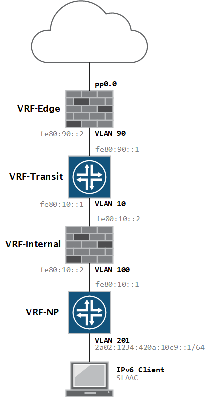
My network is running IPv6 with SLAAC and the JunOS version on my firewall does not support RDNSS, so I needed a full-featured DHCP server to hand out DNS information.

I already have a Raspberry Pi running isc-dhcp-server for my IPv4 network so I thought it would be simple to add IPv6 support. Unfortunately it was not – the ISC DHCP server does not support dual-stack natively so you need to run two independent services in parallel.

The official documentation for this is very limited and outdated, so it took a lot of blogs and forum posts to get it working, so perhaps this post will help others in their quest for DHCPv6 support 🙂

I am assuming that you have already installed and configured the DHCP server for IPv4. If not, you can do so by entering the following command.

pi@pi ~ $ sudo apt-get install isc-dhcp-server

After installation, you can start the service manually, or reboot.

pi@pi ~ $ sudo service isc-dhcp-server start
[ ok ] Starting ISC DHCP server: dhcpd.

This post focuses on the DHCPv6 part. For the actual configuration for standard DHCP, there are plenty of good guides available online.

Configuring a static IPv6 address

In case you haven’t done so, be sure to configure your device with a static IPv6 address.

pi@pi ~ $ cat /etc/network/interfaces

# iface eth0 inet dhcp

# Loopback interface

auto lo
iface lo inet loopback
auto eth0
iface eth0 inet static

# Static IPv4

address 10.6.0.36
gateway 10.6.0.1
network 10.6.0.0
netmask 255.255.255.0
broadcast 10.6.0.255

# Static IPv6

iface eth0 inet6 static
address 2a02:1234:420a:100b::10
netmask 64
gateway 2a02:1234:420a:100b::1

Restart the network interface or reboot the device to apply it.

INIT file – /etc/init.d/isc-dhcp-server6

First step is to copy the working init script, which is used by the v4 server, to a new file.

pi@pi ~ $ sudo cp /etc/init.d/isc-dhcp-server /etc/init.d/isc-dhcp-server6

This will create a new file isc-dhcp-server6 – use nano or vi to edit it.

Some of the values in the ### INIT INFO ### section need to modified to represent the new dhcpv6 service. I’ve also modified the value for the default config file, DHCPD_DEFAULT, to be /etc/default/isc-dhcp-server6 – more on that file later.

The script below shows only the first part of the script so don’t copy-paste.

#!/bin/sh
#
#

### BEGIN INIT INFO
# Provides:          isc-dhcp-server6
# Required-Start:    $remote_fs $network $syslog
# Required-Stop:     $remote_fs $network $syslog
# Should-Start:      $local_fs slapd $named
# Should-Stop:       $local_fs slapd
# Default-Start:     2 3 4 5
# Default-Stop:      0 1 6
# Short-Description: DHCPv6 server
# Description:       Dynamic Host Configuration Protocol Server for IPv6
### END INIT INFO

PATH=/sbin:/bin:/usr/sbin:/usr/bin

test -f /usr/sbin/dhcpd || exit 0

DHCPD_DEFAULT="${DHCPD_DEFAULT:-/etc/default/isc-dhcp-server6}"

# It is not safe to start if we don't have a default configuration...
if [ ! -f "$DHCPD_DEFAULT" ]; then
        echo "$DHCPD_DEFAULT does not exist! - Aborting..."
        if [ "$DHCPD_DEFAULT" = "/etc/default/isc-dhcp-server" ]; then
                echo "Run 'dpkg-reconfigure isc-dhcp-server' to fix the problem."
        fi
        exit 0
fi

. /lib/lsb/init-functions

# Read init script configuration
[ -f "$DHCPD_DEFAULT" ] && . "$DHCPD_DEFAULT"

NAME=dhcpd
DESC="ISC DHCPv6 server"
# fallback to default config file
DHCPD_CONF=${DHCPD_CONF:-/etc/dhcp/dhcpd6.conf}
# try to read pid file name from config file, with fallback to /var/run/dhcpd.pid
if [ -z "$DHCPD_PID" ]; then
        DHCPD_PID=$(sed -n -e 's/^[ \t]*pid-file-name[ \t]*"(.*)"[ \t]*;.*$/\1/p' < "$DHCPD_CONF" 2>/dev/null | head -n 1)
fi
DHCPD_PID="${DHCPD_PID:-/var/run/dhcpd.pid}"


... rest of script omitted for brevity ...

Defaults file – /etc/default/isc-dhcp-server6

This file stores the values used by the INIT script, so it’s absolutely essential that they are correct, or the service will refuse to start or will not work as expected.

Again, you can copy the existing file and modify those parameters.

sudo cp /etc/default/isc-dhcp-server /etc/default/isc-dhcp-server6

The configuration file for this example has four different values.

  • DHCPD_CONF – this value identifies the configuration file which will hold our DHCPv6 attributes.
  • DHCPD_PID – when the service is started, the process ID for the service will be written to this file
  • OPTIONS – here we need to specify the server to run in v6 mode by using the -6 knob
  • INTERFACES – the interface(s) on which the DHCP server will be listening, in my case eth0
# Defaults for isc-dhcp-server6 initscript
# sourced by /etc/init.d/isc-dhcp-server6
# installed at /etc/default/isc-dhcp-server6 by the maintainer scripts

#
# This is a POSIX shell fragment
#

# Path to dhcpd's config file (default: /etc/dhcp/dhcpd.conf).
DHCPD_CONF=/etc/dhcp/dhcpd6.conf

# Path to dhcpd's PID file (default: /var/run/dhcpd.pid).
DHCPD_PID=/var/run/dhcpd6.pid

# Additional options to start dhcpd with.
#       Don't use options -cf or -pf here; use DHCPD_CONF/ DHCPD_PID instead
OPTIONS="-6"

# On what interfaces should the DHCP server (dhcpd) serve DHCP requests?
#       Separate multiple interfaces with spaces, e.g. "eth0 eth1".
INTERFACES="eth0"

Config file – /etc/dhcp/dhcpd6.conf

This file, just like in the IPv4 version, contains the global DHCP options and the subnet statements, reservations, etc. I am using it in conjunction with SLAAC, so DHCPv6 is only used to hand out the DNS info.

Note – For IPv6 subnets, you need to use the subnet6 statement.

# The ddns-updates-style parameter controls whether or not the server will
# attempt to do a DNS update when a lease is confirmed.
ddns-update-style none;

# Option definitions common to all supported networks...
default-lease-time 600;
max-lease-time 7200;

# This DHCP server is the official DHCP server for the local network
authoritative;

# Use this to send dhcp log messages to a different log file (you also
# have to hack syslog.conf to complete the redirection).
log-facility local7;

# Subnet declaration
subnet6 2a02:1234:420a:112d::/64  {
        option dhcp6.name-servers 2a02:1234:420a:100b::10, 2001:4860:4860::8888;
        option dhcp6.domain-search "netprobe.local";
}

subnet6 2a02:1234:420a:100b::/64 {
        option dhcp6.name-servers 2a02:1234:420a:100b::10, 2001:4860:4860::8888;
        option dhcp6.domain-search "netprobe.local";
}

The DHCP6 leases file

It’s possible the service will not start because this file does not exist:

Dec  5 21:37:00 pi dhcpd: Can't open lease database /var/lib/dhcp/dhcpd6.leases: No such file or directory --
Dec  5 21:37:00 pi dhcpd:   check for failed database rewrite attempt!

Just create an empty file and it should be OK.

pi@pi / $ sudo touch /var/lib/dhcp/dhcpd6.leases

Starting the Service and verifying it

If the configuration files are correct, we can now manually start the service.

pi@pi /etc/default $ sudo service isc-dhcp-server6 start
[ ok ] Starting ISC DHCPv6 server: dhcpd.

If you are getting an error, you will usually find a clue in the /var/log/syslog files…

Verify that the second service is now running:

pi@pi /etc/default $ ps aux | grep dhcp
root      2091  0.0  1.2   6824  5368 ?        Ss   20:52   0:00 /usr/sbin/dhcpd -q -cf /etc/dhcp/dhcpd.conf -pf /var/run/dhcpd.pid eth0
root      2751  0.0  0.6   5484  2868 ?        Ss   21:18   0:00 /usr/sbin/dhcpd -q -6 -cf /etc/dhcp/dhcpd6.conf -pf /var/run/dhcpd6.pid eth0
pi        2772  0.0  0.4   3572  1944 pts/0    S+   21:19   0:00 grep --color=auto dhcp

To validate the process ID as written at service start time.

pi@pi /etc/default $ cat /var/run/dhcpd6.pid
2751

To verify that the service is listening on UDP port 547:

pi@pi /etc/default $ netstat -an | grep 547
udp6       0      0 :::547                  :::*

If you have your DHCP relays set up correctly, you can also verify communication with tcpdump. Here we can see a client is requesting information from DHCP.

pi@pi /etc/default $ sudo tcpdump -i eth0 port 547
tcpdump: verbose output suppressed, use -v or -vv for full protocol decode
listening on eth0, link-type EN10MB (Ethernet), capture size 262144 bytes
21:21:36.935479 IP6 2a02:1234:420a:112d::1.dhcpv6-server > 2a02:1234:420a:100b::10.dhcpv6-server: dhcp6 relay-fwd
21:21:36.942854 IP6 2a02:1234:420a:100b::10.dhcpv6-server > 2a02:1234:420a:112d::1.dhcpv6-server: dhcp6 relay-reply
21:21:36.951406 IP6 2a02:1234:420a:112d::1.dhcpv6-server > 2a02:1234:420a:100b::10.dhcpv6-server: dhcp6 relay-fwd
21:21:36.955437 IP6 2a02:1234:420a:100b::10.dhcpv6-server > 2a02:1234:420a:112d::1.dhcpv6-server: dhcp6 relay-reply
21:22:16.092006 IP6 2a02:1234:420a:112d::1.dhcpv6-server > 2a02:1234:420a:100b::10.dhcpv6-server: dhcp6 relay-fwd
21:22:16.094353 IP6 2a02:1234:420a:100b::10.dhcpv6-server > 2a02:1234:420a:112d::1.dhcpv6-server: dhcp6 relay-reply
21:22:16.169193 IP6 2a02:1234:420a:112d::1.dhcpv6-server > 2a02:1234:420a:100b::10.dhcpv6-server: dhcp6 relay-fwd
21:22:16.171748 IP6 2a02:1234:420a:100b::10.dhcpv6-server > 2a02:1234:420a:112d::1.dhcpv6-server: dhcp6 relay-reply

Auto-starting the service at boot

To add the new service to the initialization scripts, enter the following command.

pi@pi ~ $ sudo update-rc.d isc-dhcp-server6 defaults
update-rc.d: using dependency based boot sequencing
pi@pi ~ $

After a reboot, you should again have two running instances of the dhcpd service – one with the -6 option.

pi@pi ~ $ ps aux | grep dhcp
root      2100  0.0  1.1   6824  5120 ?        Ss   21:30   0:00 /usr/sbin/dhcpd -q -cf /etc/dhcp/dhcpd.conf -pf /var/run/dhcpd.pid eth0
root      2135  0.0  0.6   5484  3048 ?        Ss   21:30   0:00 /usr/sbin/dhcpd -q -6 -cf /etc/dhcp/dhcpd6.conf -pf /var/run/dhcpd6.pid eth0
pi        2356  0.0  0.4   3568  1836 pts/0    S+   21:32   0:00 grep --color=auto dhcp

If everything went well, your clients should now be picking up the DNS servers (or other DHCPv6 information) from your new DHCPv6 server.

If this guide does not work for you, please let me know in the comments!

IPv6 on JunOS – Static Routing

In my previous post I configured IPv6 with Prefix Delegation. IPv6-PD is alright for a simple topology but it is very, very limiting and seems quite complicated to implement when you have many subnets in a complex topology.

This post will cover static IPv6 routing. Ideally I would have implemented OSPFv3 to handle dynamic routing but sadly, my switches do not support that feature, even with the EFL license.

Lab Topology

Here is a small part of my network which I’ll be using to test it.

IPv6 Topology

Notice that the client VLAN is the only segment with a globally routed IPv6 address. With IPv6, it is perfectly fine to use only link-local (non-routed) addressing on your transit networks, and in fact it has several benefits! If you’re curious what those benefits are, you can read all about it in RFC7407 by Eric Vyncke and Michael Behringer.

Addressing configuration

My provider has assigned me two static prefixes to me. These are not the real ones btw 🙂

IPv6 LAN prefix 	2a02:1234:420a::/48
IPv6 WAN prefix 	2a02:1234:8401:9a00::/64

First, let’s configure our WAN interface with a static IP address in the WAN range.

[edit]
admin@NPFW01# set interfaces pp0 unit 0 family inet6 address 2a02:1234:8401:9a00::1/64

As I’m using PPPoE, I will need to add a static default route (::/0) with the pp0.0 interface as next-hop. Also, I’m using VRFs so I need to add it under the right routing instance.

[edit routing-instances VRF-Edge]
admin@NPFW01# set routing-options rib VRF-Edge.inet6.0 static route ::/0 next-hop pp0.0

A quick ping to Google to verify that we have IPv6 connectivity on the external interface.

admin@NPFW01> ping inet6 2001:4860:4860::8888 routing-instance VRF-Edge source 2a02:1234:8401:9a00::1 rapid count 10
PING6(56=40+8+8 bytes) 2a02:1234:8401:9a00::1 --> 2001:4860:4860::8888
!!!!!!!!!!
--- 2001:4860:4860::8888 ping6 statistics ---
10 packets transmitted, 10 packets received, 0% packet loss
round-trip min/avg/max/std-dev = 30.980/31.647/32.716/0.444 ms

So far, so good. Let’s configure the internal interfaces now.

Configuration for the link-local addresses on the Firewall:

[edit interfaces ae0 unit 90 family inet6]
admin@NPFW01# show
address fe80:90::2/64;
[edit interfaces ae1 unit 10 family inet6]
admin@NPFW01# show
address fe80:10::2/64;
[edit interfaces ae1 unit 100 family inet6]
admin@NPFW01# show
address fe80:100::2/64;

And for the switch:

{master:0}[edit interfaces vlan unit 10 family inet6]
admin@NPSWC01# show
address fe80:10::1/64;
{master:0}[edit interfaces vlan unit 90 family inet6]
admin@NPSWC01# show
address fe80:90::1/64;
{master:0}[edit interfaces vlan unit 100 family inet6]
admin@NPSWC01# show
address fe80:100::1/64;
{master:0}[edit interfaces vlan unit 101 family inet6]
admin@NPSWC01# show
address fe80:101::1/64;

In my case, the interfaces are already in the right routing instances so I don’t need to add them anymore. Don’t forget this step though, if you are recreating this in your own lab.

After a commit, we can confirm reachability between the devices inside their routing instances.

admin@NPSWC01> ping fe80:90::2 routing-instance VRF-Transit source fe80:90::1 rapid count 5
PING6(56=40+8+8 bytes) fe80:90::1 --> fe80:90::2
!!!!!
--- fe80:90::2 ping6 statistics ---
5 packets transmitted, 5 packets received, 0% packet loss
round-trip min/avg/max/std-dev = 3.981/4.689/6.566/0.947 ms
admin@NPSWC01> ping fe80:10::2 routing-instance VRF-Transit source fe80:10::1 rapid count 5
PING6(56=40+8+8 bytes) fe80:10::1 --> fe80:10::2
!!!!!
--- fe80:10::2 ping6 statistics ---
5 packets transmitted, 5 packets received, 0% packet loss
round-trip min/avg/max/std-dev = 4.181/5.018/6.296/0.731 ms
admin@NPSWC01> ping fe80:100::2 routing-instance VRF-NP source fe80:100::1 rapid count 5
PING6(56=40+8+8 bytes) fe80:100::1 --> fe80:100::2
!!!!!
--- fe80:100::2 ping6 statistics ---
5 packets transmitted, 5 packets received, 0% packet loss
round-trip min/avg/max/std-dev = 3.924/4.819/5.715/0.575 ms

Both devices should now have an entry for eachother in the IPv6 neighbour tables, which is the equivalent of the v4 ARP table.

admin@NPSWC01> show ipv6 neighbors
IPv6 Address                 Linklayer Address  State       Exp Rtr Secure Interface
fe80:10::2                   a8:d0:e5:d3:2a:81  stale       927 yes no      vlan.10
fe80:90::2                   a8:d0:e5:d3:2a:80  stale       896 yes no      vlan.90
fe80:100::2                  a8:d0:e5:d3:2a:81  stale       887 yes no      vlan.100

Client network addressing

Last step is to assign the VLAN201 interface with a publically routed interface. I will be configuring this address: 2a02:1234:420a:10c9::1/64

There are probably more elegant addressing designs but this is what I came up with:

  • The first 48 bits are our globally routed prefix.
  • For the next 16 bits, I’ve used the leading 4 bits to represent the site number. This is my first site, so number 1.
  • The last 12 bits represent the VLAN number in hexadecimal notation, as there are 4096 vlans available in the dot1q standard – VLAN201 is C9 in hex!

Granted, it’s not the most scalable solution, as it only gives me 15 more sites and it wastes a lot of addresses but hey, this is not a multinational yet! 🙂

Here’s the configuration for the VLAN201 SVI:

{master:0}[edit interfaces vlan unit 201 family inet6]
admin@NPSWC01# show
address 2a02:1234:420a:10c9::1/64;

Enabling Router Advertisements

To enable dynamic address assignments (SLAAC) for the clients behind it, we also need to enable router advertisements on this interface. The other-stateful-configuration command will add the O-Flag to the advertisements, so we can later add the additional DNS information via DHCPv6.

{master:0}[edit protocols router-advertisement interface vlan.201]
admin@NPSWC01# show
other-stateful-configuration;
prefix 2a02:1234:420a:10c9::/64;
}

After committing, the client has assigned itself an IPv6 based on the received router advertisements.

Ethernet adapter Ethernet:

   Connection-specific DNS Suffix  . : ***-networks.local
   IPv6 Address. . . . . . . . . . . : 2a02:1234:420a:10c9:b1d1:660c:ac69:c5f8
   Temporary IPv6 Address. . . . . . : 2a02:1234:420a:10c9:3c71:b6f2:e93f:67ab
   Link-local IPv6 Address . . . . . : fe80::b1d1:660c:ac69:c5f8%6
   IPv4 Address. . . . . . . . . . . : 10.255.1.13
   Subnet Mask . . . . . . . . . . . : 255.255.255.128
   Default Gateway . . . . . . . . . : fe80::5e45:27ff:fee7:af81%6
                                       10.255.1.1

The basics are now in place. Now we will add some routing to make this prefix reachable.

Configuring static routes

As mentioned, my EX2200 switches do not support OSPFv3 so static routing is the only option for now…

Note – If you are using link-local addresses as the next-hop, you must use the qualified-next-hop statement with the interface in question.

Static routes, using link-local addresses, added on the switch’s routing-instances:

{master:0}[edit routing-instances VRF-Transit routing-options]
admin@NPSWC01# show
rib VRF-Transit.inet6.0 {
    static {
        route ::/0 {
            qualified-next-hop fe80:90::2 {
                interface vlan.90;
            }
        }
        route 2a02:1234:420a:10c9::/64 {
            qualified-next-hop fe80:10::2 {
                interface vlan.10;
            }
        }
    }
}
{master:0}[edit routing-instances VRF-NP routing-options]
admin@NPSWC01# show
rib VRF-NP.inet6.0 {
    static {
        route ::/0 {
            qualified-next-hop fe80:100::2 {
                interface vlan.100;
            }
        }
    }
}

And the routes on the firewall:

[edit routing-instances VRF-Internal routing-options]
admin@NPFW01# show
rib VRF-Internal.inet6.0 {
    static {
        route ::/0 {
            qualified-next-hop fe80:10::1 {
                interface ae1.10;
            }
        }
        route 2a02:1234:420a:10c9::/64 {
            qualified-next-hop fe80:100::1 {
                interface ae1.100;
            }
        }
    }
}
admin@NPFW01# show
rib VRF-Edge.inet6.0 {
    static {
        route ::/0 next-hop pp0.0;
        route 2a02:1234:420a:10c9::/64 {
            qualified-next-hop fe80:90::1 {
                interface ae0.90;
            }
        }
    }
}

After adding this configuration, and assuming that the necessary firewall policies are in place, the client can now ping outbound to the internet.

C:\Users\user>ping 2001:4860:4860::8888

Pinging 2001:4860:4860::8888 with 32 bytes of data:
Reply from 2001:4860:4860::8888: time=30ms
Reply from 2001:4860:4860::8888: time=31ms
Reply from 2001:4860:4860::8888: time=30ms

Ping statistics for 2001:4860:4860::8888:
    Packets: Sent = 4, Received = 4, Lost = 0 (0% loss),
Approximate round trip times in milli-seconds:
    Minimum = 30ms, Maximum = 31ms, Average = 30ms

That’s all it takes to implement static routing for IPv6, easy-peasy!

IPv6 on Juniper SRX – Prefix Delegation & DHCPv6

I’m currently setting up IPv6 in my own office so I thought it would be worth documenting the configuration I’m adding on my Juniper equipment to make it all work.

I have an internet subscription with a static IPv4 address and also included with it is a /48 static IPv6 prefix. There are two ways I can set it up: static configuration or “semi-automatic” by using Prefix Delegation. This article discusses the latter and in my next post I will document the static configuration, as that’s what I will ultimately be using.

First Things First – Enabling IPv6 Forwarding

Before you can start using IPv6 on the SRX, the device needs to be explicitly configured to forward V6 traffic. This because, by default, the forwarding mode for IPv6 is set to drop. You can verify this on the command line – as shown below, the default forwarding mode for Inet6 traffic is drop:

np@NP-FW01> show security flow status
  Flow forwarding mode:
    Inet forwarding mode: flow based
    Inet6 forwarding mode: drop
    MPLS forwarding mode: drop
    ISO forwarding mode: drop
  Flow trace status
    Flow tracing status: off
  Flow session distribution
    Distribution mode: RR-based
  Flow ipsec performance acceleration: off
  Flow packet ordering
    Ordering mode: Hardware

To activate it, you must change the forwarding mode. There are three modes to choose from: drop (default), flow-based and packet-based.

[edit]
np@NP-FW01# set security forwarding-options family inet6 mode ?
Possible completions:
  drop                 Disable forwarding
  flow-based           Enable flow-based forwarding
  packet-based         Enable packet-based forwarding

I’m using the SRX as a stateful firewall, so I’ll configure flow-based and commit. JunOS will warn you that the change is active only after a device reboot, so I’ll reboot the SRX and continue below.

[edit]
np@NP-FW01# set security forwarding-options family inet6 mode flow-based
[edit]
np@NP-FW01# show | compare
[edit security]
+   forwarding-options {
+       family {
+           inet6 {
+               mode flow-based;
+           }
+       }
+   }
[edit]
np@NP-FW01# commit
warning: You have enabled/disabled inet6 flow.
You must reboot the system for your change to take effect.
If you have deployed a cluster, be sure to reboot all nodes.
commit complete

After the reboot, the forwarding mode is set to flow based and we can start implementing IPv6.

np@NP-FW01> show security flow status
  Flow forwarding mode:
    Inet forwarding mode: flow based
    Inet6 forwarding mode: flow based
    MPLS forwarding mode: drop
    ISO forwarding mode: drop
  Flow trace status
    Flow tracing status: off
  Flow session distribution
    Distribution mode: RR-based
  Flow ipsec performance acceleration: off
  Flow packet ordering
    Ordering mode: Hardware

Configuring IPv6 with Prefix Delegation

Prefix delegation is a simple method to automate the assignment of IPv6 prefixes on subscriber equipment. The CPE (in my case the SRX) informs the upstream router, called the Broadband Network Gateway (BNG) that it wants to use Prefix Delegation. The BNG retrieves the prefix for the subscriber and announces the /48 back to the CPE, after which both sides confirm the prefix allocation. The CPE will then automatically divide the /48 into smaller /64 subnets on the LAN interfaces it has configured for PD Router Advertisements.

If you want to find out exactly how it works, you can find more information in RFC3633

First, we configure the outside interface, pp0.0 in my case. Notice that we are configuring this under family inet6.

The DHCPv6 client is activated on the outside, ISP-facing interface. Some PD-specific configuration is added and we will request the DNS server addresses from the provider.

[edit interfaces pp0 unit 0 family inet6]
np@NP-FW01# show
dhcpv6-client {
    client-type statefull;
    client-ia-type ia-pd;
    rapid-commit;
    client-identifier duid-type duid-ll;
    req-option dns-server;
    retransmission-attempt 0;
}

The LAN interface, in my case ae0.311, on which I will further delegate the prefix, is specified. Showing this separately as it’s important not to miss this one! 🙂

[edit interfaces pp0 unit 0 family inet6]
np@NP-FW01# set dhcpv6-client update-router-advertisement interface ae0.311

The last step is to allow DHCPv6 packets on the security zone inbound traffic. Could be that you need to add it under the interface, if you specified it further down on that level.

[edit security zones security-zone edge-untrust]
np@NP-FW01# set host-inbound-traffic system-services dhcpv6

If you want to use this on the LAN segment, you will also need to enable DHCPv6 on that security zone and interface. I’m using a guest VLAN for testing so I’ll enable it there.

[edit]
np@NP-FW01# set security zones security-zone edge-guest host-inbound-traffic system-services dhcpv6

After a commit, we see that interface ae0.311 now has a public IPv6 address with a /64 mask.

np@NP-FW01> show interfaces terse
Interface               Admin Link Proto    Local                 Remote

 ae0.311                 up    up   inet     192.168.200.1/24
                                   inet6    2a02:1234:420a:1::1/64
                                            fe80::aad0:e501:37d3:2a80/64
...

Notice that the SRX has taken the original /48 prefix and automatically derived a /64 subnet from it for interface ae0.311: 2a02:1234:420a:1::1/64 .

Note – real prefix modified for obvious reasons 🙂

Before we can test reachability, we will need to configure the default route via pp0.0. I’m using routing-instances (VRFs) so I will add it on my external edge instance.

[edit routing-instances VRF-Edge routing-options]
np@NP-FW01# show
rib VRF-Edge.inet6.0 {
    static {
        route ::/0 next-hop pp0.0;
    }
}

With the default route in place, we should be able to ping a public v6 address from this VRF. Below, we are pinging Google DNS, from the interface with Prefix Delegation.

np@NP-FW01> ping 2001:4860:4860::8888 routing-instance VRF-Edge rapid count 10 source 2a02:1234:420a:1::1
PING6(56=40+8+8 bytes) 2a02:1234:420a:1::1 --> 2001:4860:4860::8888
!!!!!!!!!!
--- 2001:4860:4860::8888 ping6 statistics ---
10 packets transmitted, 10 packets received, 0% packet loss
round-trip min/avg/max/std-dev = 31.811/32.841/35.861/1.163 ms

Success! This shows that IPv6-PD is working as expected and that the delegated prefix is globally reachable.

After connecting a test machine inside the VLAN, we can confirm that the router advertisements are working as expected. The client has taken the /64 prefix and assigned itself an EUI-64 address.

Ethernet adapter Ethernet:

   Connection-specific DNS Suffix  . : netprobe.guest
   Description . . . . . . . . . . . : Intel(R) Ethernet Connection (4) I219-V
   Physical Address. . . . . . . . . : C8-5B-76-BC-04-6E
   DHCP Enabled. . . . . . . . . . . : Yes
   Autoconfiguration Enabled . . . . : Yes
   IPv6 Address. . . . . . . . . . . : 2a02:1234:420a:1:103f:efd8:f2f7:d0cf(Preferred)
   Temporary IPv6 Address. . . . . . : 2a02:1234:420a:1:293c:fd60:c216:8123(Preferred)
   Link-local IPv6 Address . . . . . : fe80::103f:efd8:f2f7:d0cf%14(Preferred)
   IPv4 Address. . . . . . . . . . . : 192.168.200.13(Preferred)
   Subnet Mask . . . . . . . . . . . : 255.255.255.0
   Lease Obtained. . . . . . . . . . : zondag 12 november 2017 15:23:41
   Lease Expires . . . . . . . . . . : maandag 13 november 2017 15:26:16
   Default Gateway . . . . . . . . . : fe80::aad0:e501:37d3:2a80%14
                                       192.168.200.1
   DHCP Server . . . . . . . . . . . : 192.168.200.1
   DHCPv6 IAID . . . . . . . . . . . : 63462262
   DHCPv6 Client DUID. . . . . . . . : 00-01-00-01-20-35-58-1B-C8-5B-76-BC-04-6E
   DNS Servers . . . . . . . . . . . : 208.67.220.123
                                       208.67.222.123
   NetBIOS over Tcpip. . . . . . . . : Enabled

Now, this part seems to be working fine, but you may notice that the client has not received any IPv6 name servers.
This is because the client uses SLAAC to configure its v6 address based on the Router Advertisements, but it still relies on DHCPv6 to receive any special information such as DNS servers.

To make this work, we need to add a few more bits of configuration to use the SRX as a a DHCPv6 server.

Handing out DNS servers via DHCPv6

First, configure the DHCPv6 pool with the prefix and the DNS server you want to hand out. I’m using Google DNS here.

np@NP-FW01# show routing-instances VRF-Edge access address-assignment
pool vlan311-dhcpv6 {
    family inet6 {
        prefix 2a02:1234:420a:1::/64;
        dhcp-attributes {
            dns-server {
                2001:4860:4860::8888;
                2001:4860:4860::8844;
            }
        }
    }
}

Next, configure the internal DHCPv6 server under system services, referring to the pool you just created – add it under routing-instances if required!

np@NP-FW01# show routing-instances VRF-Edge system services dhcp-local-server
dhcpv6 {
    overrides {
        interface-client-limit 100;
        process-inform {
            pool vlan311-dhcpv6;
        }
    }
    group ipv6 {
        interface ae0.311;
    }
}
group group-vlan311 {
    interface ae0.311;
}

Activate Router Advertisements for your outside interface. It doesn’t seem to work for me without this.

[edit]
np@NP-FW01# show protocols router-advertisement
interface pp0.0;

The following bit controls the Router Advertisements on the delegated interface and activates the O-Flag (Other Information) on the RAs.

[edit interfaces pp0 unit 0 family inet6 dhcpv6-client update-router-advertisement interface ae0.311]
+         other-stateful-configuration;
+         max-advertisement-interval 6;
+         min-advertisement-interval 3;

After adding this configuration, we see the client has now successfully picked up the new DNS settings.

Ethernet adapter Ethernet:

   Connection-specific DNS Suffix  . : netprobe.guest
   Description . . . . . . . . . . . : Intel(R) Ethernet Connection (4) I219-V
   Physical Address. . . . . . . . . : C8-5B-76-BC-04-6E
   DHCP Enabled. . . . . . . . . . . : Yes
   Autoconfiguration Enabled . . . . : Yes
   IPv6 Address. . . . . . . . . . . : 2a02:1234:420a:1:103f:efd8:f2f7:d0cf(Preferred)
   Temporary IPv6 Address. . . . . . : 2a02:1234:420a:1:488c:f549:1e67:254c(Preferred)
   Link-local IPv6 Address . . . . . : fe80::103f:efd8:f2f7:d0cf%14(Preferred)
   IPv4 Address. . . . . . . . . . . : 192.168.200.13(Preferred)
   Subnet Mask . . . . . . . . . . . : 255.255.255.0
   Lease Obtained. . . . . . . . . . : zondag 12 november 2017 15:23:41
   Lease Expires . . . . . . . . . . : maandag 13 november 2017 17:08:57
   Default Gateway . . . . . . . . . : fe80::aad0:e501:37d3:2a80%14
                                       192.168.200.1
   DHCP Server . . . . . . . . . . . : 192.168.200.1
   DHCPv6 IAID . . . . . . . . . . . : 63462262
   DHCPv6 Client DUID. . . . . . . . : 00-01-00-01-20-35-58-1B-C8-5B-76-BC-04-6E
   DNS Servers . . . . . . . . . . . : 2001:4860:4860::8888
                                       2001:4860:4860::8844
                                       208.67.220.123
                                       208.67.222.123
   NetBIOS over Tcpip. . . . . . . . : Enabled

After adding a security policy that allows IPv6 traffic, the client can succesfully communicate over IPv6.

C:\Users\Simon>nslookup - 2001:4860:4860::8888
Default Server:  google-public-dns-a.google.com
Address:  2001:4860:4860::8888

> google.com
Server:  google-public-dns-a.google.com
Address:  2001:4860:4860::8888

Non-authoritative answer:
Name:    google.com
Addresses:  2a00:1450:400e:80b::200e
          172.217.20.110

C:\Users\Simon>ping -6 www.google.com

Pinging www.google.com [2a00:1450:400e:806::2004] with 32 bytes of data:
Reply from 2a00:1450:400e:806::2004: time=30ms
Reply from 2a00:1450:400e:806::2004: time=31ms
Reply from 2a00:1450:400e:806::2004: time=30ms

Ping statistics for 2a00:1450:400e:806::2004:
    Packets: Sent = 4, Received = 4, Lost = 0 (0% loss),
Approximate round trip times in milli-seconds:
    Minimum = 30ms, Maximum = 31ms, Average = 30ms

Verification Commands

Checking which prefix was allocated to you by the ISP – don’t forget to specify the routing-instance if you are using them.

np@NP-FW01> show dhcpv6 client binding routing-instance VRF-Edge

IP/prefix                       Expires     State      ClientType    Interface       Client DUID
2a02:1234:420a::/48              2590728     BOUND      STATEFUL      pp0.0           LL0x29-a8:d0:e5:d3:2a:47

You can renew the prefix lease this way:

np@NP-FW01> request dhcpv6 client renew routing-instance VRF-Edge interface pp0.0

Displaying the IPv6 neighbours – this is similar to your ARP table in IPv4.

np@NP-FW01> show ipv6 neighbors
IPv6 Address                 Linklayer Address  State       Exp Rtr Secure Interface
2a02:1234:420a:1:488c:f549:1e67:254c
                             c8:5b:76:bc:04:6e  stale       1017 no no      ae0.311
fe80::103f:efd8:f2f7:d0cf    c8:5b:76:bc:04:6e  stale       363 no  no      ae0.311

Statistics for the DHCPv6 server:

np@NP-FW01> show dhcpv6 server statistics routing-instance VRF-Edge
Dhcpv6 Packets dropped:
    Total               0

Messages received:
    DHCPV6_DECLINE             1
    DHCPV6_SOLICIT             6
    DHCPV6_INFORMATION_REQUEST 60
    DHCPV6_RELEASE             0
    DHCPV6_REQUEST             3
    DHCPV6_CONFIRM             0
    DHCPV6_RENEW               0
    DHCPV6_REBIND              0
    DHCPV6_RELAY_FORW          0
    DHCPV6_RELAY_REPL          0

Messages sent:
    DHCPV6_ADVERTISE           4
    DHCPV6_REPLY               8
    DHCPV6_RECONFIGURE         0
    DHCPV6_RELAY_REPL          0

Now, if I was running a fairly simple network with just a few subnets, I would be using Prefix Delegation but I also have a couple of L3 devices behind this firewall. Extending PD all the way down would make it overly complex, so I’ll go for static configuration with OSPFv3 in the next article.

Please let me know in the comments if this configuration did not work for you!

JNCIS-ENT – OSPF LSA types on JunOS

Going through the JNCIS-ENT course, I realized that I had forgotten so much of the details about the different LSA types and all of its intricacies. Next to being able to answer trick exam questions, knowing the LSAs and their working helps a lot when dealing with complex OSPF problems or optimizing your network topologies. As I really needed a refresher for this exam and my upcoming NP refresh I created this simple topology and tried to document as much of my findings as possible.

Lab Topology

OSPF Topology

We have four routers interconnected via OSPF. The area configuration is as follows.

  • vMX1 – RID 1.1.1.1 – connected to area 12
  • vMX2 – RID 2.2.2.2 – connected to area 12 and backbone area 0
  • vMX3 – RID 3.3.3.3 – connected to backbone area 0 and area 34
  • vMX4 – RID 4.4.4.4 – connected to area 34

Below is the standard configuration that is running on router VMX2 – Router ID, area statements and active interfaces. The other routers have similar configuration for their respective interfaces and areas.

[edit]
root@vMX2# show
routing-options {
    router-id 2.2.2.2;
}
protocols {
    ospf {
        area 0.0.0.0 {
            interface ge-0/0/0.0;
            interface lo0.0 {
                passive;
            }
        }
        area 0.0.0.12 {
            interface ge-0/0/1.0;
        }
    }
}

For now, until we move on to the Type 7 LSA, all areas are configured as standard areas. Before we start, here is an output of the LSA database on router VMX2. As it’s connected to two areas, it’s keeping two LSDBs. We’ll be using this router’s database for the first set of LSAs.

root@vMX2> show ospf database

    OSPF database, Area 0.0.0.0
 Type       ID               Adv Rtr           Seq      Age  Opt  Cksum  Len
Router  *2.2.2.2          2.2.2.2          0x80000180  2034  0x22 0x4d8   48
Router   3.3.3.3          3.3.3.3          0x8000017f  2044  0x22 0x1ab6  48
Network  172.16.23.3      3.3.3.3          0x8000017b  1794  0x22 0x7651  32
Summary *1.1.1.1          2.2.2.2          0x80000070  1784  0x22 0x4a76  28
Summary  4.4.4.4          3.3.3.3          0x80000001    53  0x22 0x809f  28
Summary *172.16.12.0      2.2.2.2          0x8000017c  1034  0x22 0x539b  28
Summary  172.16.34.0      3.3.3.3          0x8000017d  1544  0x22 0x4093  28

    OSPF database, Area 0.0.0.12
 Type       ID               Adv Rtr           Seq      Age  Opt  Cksum  Len
Router   1.1.1.1          1.1.1.1          0x80000073   253  0x22 0xd03   48
Router  *2.2.2.2          2.2.2.2          0x80000074   784  0x22 0xe0b   36
Network *172.16.12.2      2.2.2.2          0x80000071   534  0x22 0xda10  32
Summary *2.2.2.2          2.2.2.2          0x80000071   284  0x22 0x10ac  28
Summary *3.3.3.3          2.2.2.2          0x80000071    34  0x22 0xebcb  28
Summary *4.4.4.4          2.2.2.2          0x80000001    52  0x22 0xa87a  28
Summary *172.16.23.0      2.2.2.2          0x80000070  2784  0x22 0xf4fb  28
Summary *172.16.34.0      2.2.2.2          0x80000070  2534  0x22 0x855f  28

LSA Type 1 – Router LSA

The first LSA type is generated by every router participating in OSPF and lists all of the router’s links together with their associated cost, as well the OSPF neigbhours it has inside the area. Every router will flood a Router LSA for each area it is active in.

Looking at our OSPF database from before, router 2.2.2.2 has received a router LSA from router 1.1.1.1 and router 3.3.3.3 (Adv Rtr). Those LSAs are only seen in their respective areas, which demonstrates that a router LSA never leaves an area. We can further drill down to display only routers LSAs with the following command.

root@vMX2> show ospf database router

    OSPF database, Area 0.0.0.0
 Type       ID               Adv Rtr           Seq      Age  Opt  Cksum  Len
Router  *2.2.2.2          2.2.2.2          0x80000181   149  0x22 0x2d9   48
Router   3.3.3.3          3.3.3.3          0x80000180    37  0x22 0x18b7  48

    OSPF database, Area 0.0.0.12
 Type       ID               Adv Rtr           Seq      Age  Opt  Cksum  Len
Router   1.1.1.1          1.1.1.1          0x80000073  1174  0x22 0xd03   48
Router  *2.2.2.2          2.2.2.2          0x80000074  1705  0x22 0xe0b   36

If we want to get more specific and view the contents of the actual LSA, we can do so by specifying the LSA ID and adding the extensive command. Let’s see what router 1.1.1.1 is telling us about itself.

root@vMX2> show ospf database router lsa-id 1.1.1.1 extensive

    OSPF database, Area 0.0.0.12
 Type       ID               Adv Rtr           Seq      Age  Opt  Cksum  Len
Router   1.1.1.1          1.1.1.1          0x80000073  1274  0x22 0xd03   48
  bits 0x0, link count 2
  id 172.16.12.2, data 172.16.12.1, Type Transit (2)
    Topology count: 0, Default metric: 1
  id 1.1.1.1, data 255.255.255.255, Type Stub (3)
    Topology count: 0, Default metric: 0
  Topology default (ID 0)
    Type: Transit, Node ID: 172.16.12.2
      Metric: 1, Bidirectional
  Aging timer 00:38:45
  Installed 00:21:13 ago, expires in 00:38:46, sent 3d 19:45:06 ago
  Last changed 00:21:13 ago, Change count: 4

The router is advertising its two links in the LSA (link count 2). The LSA identifier is the originating router’s RID. The first link is an OSPF type Transit where it has a neighbourship with router 172.16.12.2 (data). If we configured the interface-type to p2p, we would see this as the link type. The router also has a Stub link with prefix 1.1.1.1/32, which means that this network contains only one router.

LSA Type 2 – Network LSA

The second LSA type is the Network LSA, which is generated by the Designated Router on a multi-access (broadcast or non-broadcast) segment. It lists all of the routers connected to the segment. It is generated only by the Designated Router to prevent duplicate LSAs.

Our router 2.2.2.2 has received the following network LSAs in area 12:

root@vMX2> show ospf database area 0.0.0.12 network

    OSPF database, Area 0.0.0.12
 Type       ID               Adv Rtr           Seq      Age  Opt  Cksum  Len
Network *172.16.12.2      2.2.2.2          0x8000001b  2085  0x22 0x87b9  32

Drilling down on this particular LSA, it contains the following information:

root@vMX2> ... 0.0.0.12 network lsa-id 172.16.12.2 extensive

    OSPF database, Area 0.0.0.12
 Type       ID               Adv Rtr           Seq      Age  Opt  Cksum  Len
Network *172.16.12.2      2.2.2.2          0x8000001b  2099  0x22 0x87b9  32
  mask 255.255.255.0
  attached router 2.2.2.2
  attached router 1.1.1.1
  Topology default (ID 0)
    Type: Transit, Node ID: 1.1.1.1
      Metric: 0, Bidirectional
    Type: Transit, Node ID: 2.2.2.2
      Metric: 0, Bidirectional
  Gen timer 00:15:01
  Aging timer 00:25:01
  Installed 00:34:59 ago, expires in 00:25:01, sent 00:34:57 ago
  Last changed 22:03:21 ago, Change count: 1, Ours

From this LSA, we can tell that the network has a /24 mask and that it has router 1.1.1.1 and 2.2.2.2 attached to it. It does not include a cost or metric for the routers, because from the network’s point of view, the cost to the attached routers is zero. If we wanted to know more information about a particular router, we can use the attached router ID which in turn refers to the router LSA we looked at earlier.

LSA Type 3 – Network Summary

This LSA type is generated by Area Border Routers and flooded into a particular area to represent destinations outside of the area. In the opposite direction, the ABR will also advertise prefixes from a non-backbone area back into backbone area 0 with a network LSA. They are flooded into areas where the destination prefix was not found. One thing worth noting is that this only counts for inter-area destinations learned inside the OSPF AS. Routes external to OSPF will use a different LSA type which I’ll cover later.

Again, we will view the contents of router 2.2.2.2’s database for area 12.

root@vMX2> show ospf database area 0.0.0.12 netsummary

    OSPF database, Area 0.0.0.12
 Type       ID               Adv Rtr           Seq      Age  Opt  Cksum  Len
Summary *2.2.2.2          2.2.2.2          0x800000ae  2289  0x22 0x95e9  28
Summary *3.3.3.3          2.2.2.2          0x800000ae  1689  0x22 0x7109  28
Summary *4.4.4.4          2.2.2.2          0x8000003e  1989  0x22 0x2eb7  28
Summary *172.16.23.0      2.2.2.2          0x800000ae  1389  0x22 0x783a  28
Summary *172.16.34.0      2.2.2.2          0x800000ae  1089  0x22 0x99d   28

Router 2.2.2.2, as the area border router, has generated these LSAs itself (*) and flooded them into area 12. Comparing this to the diagram and the full LSA database, we can tell that it has created network summaries for Router, Network and Summary LSAs inside area 0.

root@vMX2>show ospf database area 12 netsummary lsa-id 172.16.34.0 extensive

    OSPF database, Area 0.0.0.12
 Type       ID               Adv Rtr           Seq      Age  Opt  Cksum  Len
Summary *172.16.34.0      2.2.2.2          0x800000ae  1527  0x22 0x99d   28
  mask 255.255.255.0
  Topology default (ID 0) -> Metric: 2
  Gen timer 00:24:33
  Aging timer 00:34:33
  Installed 00:25:27 ago, expires in 00:34:33, sent 00:25:25 ago
  Last changed 5d 22:58:56 ago, Change count: 2, Ours

The LSA ID matches the destination network’s prefix. In this case, router R2 knows about the network 172.16.34.0/24 and added a cost of 2 to reach it. Router 1.1.1.1 will add this value to its own cost to ABR 2.2.2.2 to determine the ultimate cost for the route.

LSA Type 4 – ASBR Summary

When a router is advertising routes from sources external to the OSPF AS, it is called an Autonomous System Border Router (ASBR). Like any other router, it will generate a router LSA for itself (Type 1) into its own area but with a special flag E set. When this LSA is received by the other ABR, the router LSA will be converted into a Type 4 LSA when it is flooded into other areas. The LSA is flooded throughout the entire OSPF Autonomous System and lets other routers know how to reach the ASBR.

To demonstrate, I have configured router 4.4.4.4 to redistribute route 10.4.0.0/24 from its loopback interface as an external route. First, define the export policy as a policy-statement.

root@vMX4# show policy-options
policy-statement redist-direct {
    term term1 {
        from {
            protocol direct;
            interface lo0.0;
        }
        then accept;
    }
}

Then, configure OSPF to use that statement as its export policy.

root@vMX4# show protocols ospf
export redist-direct;
area 0.0.0.34 {
    interface ge-0/0/0.0;
}

We will now see an external route for 10.4.0.0/24, and an ASBR summary for 4.4.4.4 in the database on router 2.2.2.2

root@vMX2> show ospf database area 12

    OSPF database, Area 0.0.0.12
 Type       ID               Adv Rtr           Seq      Age  Opt  Cksum  Len
Router   1.1.1.1          1.1.1.1          0x800000b6  2563  0x22 0x8646  48
Router  *2.2.2.2          2.2.2.2          0x800000b8   559  0x22 0x854f  36
Network *172.16.12.2      2.2.2.2          0x8000001d   259  0x22 0x83bb  32
Summary *2.2.2.2          2.2.2.2          0x800000af  2359  0x22 0x93ea  28
Summary *3.3.3.3          2.2.2.2          0x800000af  1759  0x22 0x6f0a  28
Summary *172.16.23.0      2.2.2.2          0x800000af  1459  0x22 0x763b  28
Summary *172.16.34.0      2.2.2.2          0x800000af  1159  0x22 0x79e   28
ASBRSum *4.4.4.4          2.2.2.2          0x80000001   986  0x22 0x9a87  28
    OSPF AS SCOPE link state database
 Type       ID               Adv Rtr           Seq      Age  Opt  Cksum  Len
Extern   10.4.0.0         4.4.4.4          0x80000001    99  0x22 0xd5be  36

Let’s see what’s inside the ASBR summary…

root@vMX2> ... 12 asbrsummary lsa-id 4.4.4.4 extensive

    OSPF database, Area 0.0.0.12
 Type       ID               Adv Rtr           Seq      Age  Opt  Cksum  Len
ASBRSum *4.4.4.4          2.2.2.2          0x80000001   177  0x22 0x9a87  28
  mask 0.0.0.0
  Topology default (ID 0) -> Metric: 2
  Gen timer 00:47:03
  Aging timer 00:57:03
  Installed 00:02:57 ago, expires in 00:57:03, sent 00:02:57 ago
  Last changed 00:02:57 ago, Change count: 1, Ours

The LSA ID is the router ID of the ASBR, and router 2.2.2.2 has a cost of 2 to reach it.

For completeness’ sake, the command below shows that the LSA was originally a Type 1 in area 34 before being converted into an ASBR summary by router 3.3.3.3, when flooding it into area 0.

root@vMX3> show ospf database lsa-id 4.4.4.4

    OSPF database, Area 0.0.0.0
 Type       ID               Adv Rtr           Seq      Age  Opt  Cksum  Len
ASBRSum *4.4.4.4          3.3.3.3          0x80000001  1090  0x22 0x72ac  28

    OSPF database, Area 0.0.0.34
 Type       ID               Adv Rtr           Seq      Age  Opt  Cksum  Len
Router   4.4.4.4          4.4.4.4          0x800000b8  1091  0x22 0x68d   36

LSA Type 5 – AS External LSA

When the ASBR imports routes from outside the Autonomous System, either through static or protocol redistribution, it will flood them into its area as AS External LSAs. This type of LSA is flooded throughout the OSPF topology except for stub areas.

Router 2.2.2.2 has received the external route from ASBR router 4.4.4.4.

root@vMX2> show ospf database area 12 external
    OSPF AS SCOPE link state database
 Type       ID               Adv Rtr           Seq      Age  Opt  Cksum  Len
Extern   10.4.0.0         4.4.4.4          0x80000001   577  0x22 0xd5be  36

The original ASBR’s RID is preserved in the Advertising Router field.

root@vMX2> show ospf database area 12 lsa-id 10.4.0.0 extensive
    OSPF AS SCOPE link state database
 Type       ID               Adv Rtr           Seq      Age  Opt  Cksum  Len
Extern   10.4.0.0         4.4.4.4          0x80000001   675  0x22 0xd5be  36
  mask 255.255.255.0
  Topology default (ID 0)
    Type: 2, Metric: 0, Fwd addr: 0.0.0.0, Tag: 0.0.0.0
  Aging timer 00:48:44
  Installed 00:11:13 ago, expires in 00:48:45, sent 00:11:13 ago
  Last changed 00:11:13 ago, Change count: 1

Router 2.2.2.2 has now learned about the external route 10.4.0.0/24 and will need to recursively use ASBR 4.4.4.4 to reach it. Because the route was injected with the default Type E2, inter-area OSPF link cost is not taken into consideration, and the associated cost is zero as injected by router 4.4.4.4. Before we wrap up on this LSA type, the external route types might need some clarification.

E1 and E2 type routes

External routes or Type 5 LSAs can be imported as either Type 1 or Type 2 routes. When injecting as E2 routes, the autonomous system’s internal cost metrics are not taken into consideration when the LSA is flooded throughout the topology. This the default behaviour and it’s fine in simple stub topologies, but as OSPF is by design a cost-based protocol, using E1 routes makes more sense. This will make the routers combine the route’s original metric with the cost to reach the ASBR (Type 4 LSA), resulting in the total route cost. Let’s demonstrate…

The external route type is configured in the routing-policy. Here’s an example of my export policy before making any changes.

[edit policy-options policy-statement redist-direct]
root@vMX4# show
term term1 {
    from {
        protocol direct;
        interface lo0.0;
    }
    then accept;
}

Now, if we want to set the route as an E1, we define this an action in the policy term. I will import the route with a default cost of 5 and set them as type E1.

[edit policy-options policy-statement redist-direct]
root@vMX4# set term term1 then external type 1

[edit policy-options policy-statement redist-direct]
root@vMX4# set term term1 then metric 5

[edit policy-options policy-statement redist-direct]
root@vMX4# show
term term1 {
    from {
        protocol direct;
        interface lo0.0;
    }
    then {
        metric 5;
        external {
            type 1;
        }
        accept;
    }
}

After a commit, we have the following LSA in our database.

root@vMX2> show ospf database external lsa-id 10.4.0.0 extensive
    OSPF AS SCOPE link state database
 Type       ID               Adv Rtr           Seq      Age  Opt  Cksum  Len
Extern   10.4.0.0         4.4.4.4          0x8000003d    86  0x22 0xcc7   36
  mask 255.255.255.0
  Topology default (ID 0)
    Type: 1, Metric: 5, Fwd addr: 0.0.0.0, Tag: 0.0.0.0
  Aging timer 00:58:33
  Installed 00:01:24 ago, expires in 00:58:34, sent 00:01:24 ago
  Last changed 00:01:24 ago, Change count: 4

The same route is now received as E1 (Type: 1). The cost was injected with a cost of 5 but when we validate in the RIB, we see it has a metric of 7 for the route.

root@vMX2> show route 10.4.0.0 | match metric
10.4.0.0/24        *[OSPF/150] 00:02:09, metric 7, tag 0

This confirms that Total Cost = Cost of Route (5) + Cost to ASBR (2)

LSA Type 7 – NSSA External

When an area is configured as a stub, external routes or Type 5 LSAs will not be allowed in and commonly replaced by one default route. This reduces the LSDB size on the stub routers and keeps the topology simple, but there might be cases where you do need external routes to originate in those stub areas. For these cases, the Not-So-Stubby Area was designed. This allows you to place an ASBR in the stub area and still import external routes, but this time with a special LSA type. When it traverses to the backbone area, the stub-to-backbone ABR will convert the NSSA External LSA into a standard Type-5 External LSA.

To demonstrate, I have converted area 34 to a NSSA on both router 3 and router 4.

root@vMX4# show
export redist-direct;
area 0.0.0.34 {
    nssa;
    interface ge-0/0/0.0;
}

The Type 5 LSA that was previously flooded by router 4.4.4.4 will now be shown as an NSSA External LSA.

root@vMX4> show ospf database

    OSPF database, Area 0.0.0.34
 Type       ID               Adv Rtr           Seq      Age  Opt  Cksum  Len
Router   3.3.3.3          3.3.3.3          0x80000005   227  0x20 0xcc84  36
Router  *4.4.4.4          4.4.4.4          0x80000004   226  0x20 0x8dbc  36
Network *172.16.34.4      4.4.4.4          0x80000002   226  0x20 0x3dee  32
Summary  1.1.1.1          3.3.3.3          0x80000002   227  0x20 0x31fa  28
Summary  2.2.2.2          3.3.3.3          0x80000002   227  0x20 0xf830  28
Summary  3.3.3.3          3.3.3.3          0x80000002   227  0x20 0xc065  28
Summary  172.16.12.0      3.3.3.3          0x80000002   227  0x20 0x5512  28
Summary  172.16.23.0      3.3.3.3          0x80000002   227  0x20 0xd18b  28
NSSA    *10.4.0.0         4.4.4.4          0x80000002   226  0x28 0x2cf7  36

On the last line, we have our Type 7 LSA. Inside it we find the following information…

root@vMX4> show ospf database lsa-id 10.4.0.0 extensive

    OSPF database, Area 0.0.0.34
 Type       ID               Adv Rtr           Seq      Age  Opt  Cksum  Len
NSSA    *10.4.0.0         4.4.4.4          0x80000002   262  0x28 0x2cf7  36
  mask 255.255.255.0
  Topology default (ID 0)
    Type: 1, Metric: 5, Fwd addr: 172.16.34.4, Tag: 0.0.0.0
  Gen timer 00:45:37
  Aging timer 00:55:37
  Installed 00:04:22 ago, expires in 00:55:38, sent 00:04:22 ago
  Last changed 00:04:22 ago, Change count: 2, Ours

The LSA contents are almost identical to the previous one, except that the router’s LAN IP is now in the Fwd address field.

Hopping back to router 2, we see the same prefix has been received as an External, Type 5, LSA.

root@vMX2> show ospf database lsa-id 10.4.0.0 extensive
    OSPF AS SCOPE link state database
 Type       ID               Adv Rtr           Seq      Age  Opt  Cksum  Len
Extern   10.4.0.0         3.3.3.3          0x80000002   715  0x22 0xc06f  36
  mask 255.255.255.0
  Topology default (ID 0)
    Type: 1, Metric: 5, Fwd addr: 172.16.34.4, Tag: 0.0.0.0
  Aging timer 00:48:05
  Installed 00:11:52 ago, expires in 00:48:05, sent 00:11:50 ago
  Last changed 00:12:16 ago, Change count: 1

Interestingly, the advertising router is no longer 4.4.4.4 but 3.3.3.3, as this was the one that generated the Type 5 LSA. Because this router is now also acting as an ASBR, it advertised its own Router LSA with the E bit set which is into an ASBR summary LSA by router 2.2.2.2 when it is sent into area 12.

root@vMX2> show ospf database asbrsummary

    OSPF database, Area 0.0.0.12
 Type       ID               Adv Rtr           Seq      Age  Opt  Cksum  Len
ASBRSum *3.3.3.3          2.2.2.2          0x80000001  1006  0x22 0xbe68  28

From the perspective of the other routers, this device is now the source of the external route and the same logic we saw earlier is applied.

There you go, some of the things I’ve learned labbing LSAs. If you have anything to add, or spotted some inaccuracy, I’m always happy to hear in the comments!

Consistent software versions on dual-partition JunOS devices

Modern Junos devices have dual boot partitions, each with their own copy of the operating system. This ensures that the device will boot if storage or other boot-related issues are detected on the primary boot partition.

However, when you manually update the software, it is only updated on one of the partitions which is then set as the boot partition. The second, original, partition will keep running on the previous version until it is manually updated as well. This might be an advantage if you are testing a new software version and want to quickly roll back to the old one. It could also wreak havoc if you are inadvertently falling back to a pre-historic software version that is missing or not compatible with some of the features you’ve since enabled. If you have found a stable software version, it’s best to keep both partitions in sync. Here’s how to do it…

Identifying a software mismatch

The first hint is given at boot time. Right before the login prompt and banner, the console will alert you of the software version disparity.

kern.securelevel: -1 -> 1
Creating JAIL MFS partition...
JAIL MFS partition created
Boot media /dev/ad0 has dual root support


WARNING: JUNOS versions running on dual partitions are not same


** /dev/ad0s1a
FILE SYSTEM CLEAN; SKIPPING CHECKS
clean, 242154 free (34 frags, 30265 blocks, 0.0% fragmentation)

You can also find out from operational mode. The command below will show you the software versions on both of the partitions.

netprobe@netfilter> show system snapshot media internal
Information for snapshot on       internal (/dev/ad0s1a) (backup)
Creation date: Jul 31 11:13:12 2014
JUNOS version on snapshot:
  junos  : 12.1X44-D35.5-domestic
Information for snapshot on       internal (/dev/ad0s2a) (primary)
Creation date: Mar 4 19:53:11 2016
JUNOS version on snapshot:
  junos  : 12.1X46-D40.2-domestic

As you can see from the output, we are currently running on partition /dev/ad0s2a, which has a newer software version than the first partition /dev/ad0s1a.

Cloning the primary partition

To get the software version from our now-primary partition over to the backup, the system will first format the backup partition and then clone the contents. This process is initiated with the command below.

netprobe@netfilter> request system snapshot slice alternate
Formatting alternate root (/dev/ad0s1a)...
Copying '/dev/ad0s2a' to '/dev/ad0s1a' .. (this may take a few minutes)
The following filesystems were archived: /

After the cloning process you might need to reboot the device, depending on the model. If all went well, you will no longer see the warning prompt for version mismatch:

Creating JAIL MFS partition...
JAIL MFS partition created
Boot media /dev/ad0 has dual root support
** /dev/ad0s1a
FILE SYSTEM CLEAN; SKIPPING CHECKS

And voila, the snapshot command will now show the same SW version on both partitions.

netprobe@netfilter> show system snapshot media internal
Information for snapshot on       internal (/dev/ad0s1a) (backup)
Creation date: Mar 4 21:45:37 2016
JUNOS version on snapshot:
  junos  : 12.1X46-D40.2-domestic
Information for snapshot on       internal (/dev/ad0s2a) (primary)
Creation date: Mar 4 21:48:51 2016
JUNOS version on snapshot:
  junos  : 12.1X46-D40.2-domestic

On EX switches, you can alternate between boot partitions by entering this command.

request system reboot slice alternate media internal

Unfortunately this doesn’t seem to work on SRX devices, at least not on the branch devices I’ve worked with so far. If anyone knows how to make this work on these SRXs I would love to hear about it!

Allowing inbound DHCP requests on a Cisco ZBFW

I came across an interesting one today, where a Cisco Zone-Based Firewall needed to be reconfigured to serve DHCP for a segment connected to it in a zone called “Guest”. It already had a policy-map configured for traffic from Guest to Self, which had ACLs for SSH management.

First I tried adding these two lines to that ACL, in the existing class-map

 permit udp any any eq bootpc
 permit udp any any eq bootps

Although I did see the ACL match counters increment, DHCP was not handing out addresses yet. A quick search led me to this page on the Cisco site. In the last paragraph, they state the following:

If the routers’ inside interface is acting as a DHCP server and if the clients that connect to the inside interface are the DHCP clients, this DHCP traffic is allowed by default if there is no inside-to-self or self-to-inside zone policy.
However, if either of those policies does exist, you need to configure a pass action for the traffic of interest (UDP port 67 or UDP port 68) in the zone pair service policy.

In my case, there was a policy configured but with the action set to inspect. To fix it, I had to add a new ACL and class-map to the Guest-Self policy-map.

New ACL that matches the DHCP traffic. The source and destination is set to any because of the DHCP request format.

ip access-list extended Guest-Self-DHCP-ACL
 permit udp any any eq bootpc
 permit udp any any eq bootps

Tie the ACL to a new inspect class map:

class-map type inspect match-any Guest-Self-DHCP-CMap
 match access-group name Guest-Self-DHCP-ACL

And finally, add the class-map to the policy-map with the pass action

policy-map type inspect Guest-Self-PMap
 class type inspect Guest-Self-CMap
  inspect
 class type inspect Guest-Self-DHCP-CMap
  pass log
 class class-default
  drop

After that the clients started receciving IP addresses again.

ZBFW-ROUTER#show ip dhcp binding
Bindings from all pools not associated with VRF:
IP address          Client-ID/              Lease expiration        Type
                    Hardware address/
                    User name
192.168.200.201     014d.970e.4136.af       Oct 21 2015 10:43 AM    Automatic

Route-based IPsec tunnels on the SRX

Expanding on the basic branch setup from my previous labs, I added another virtual SRX to the topology to exercise the VPN stuff. As the “ISP” router, I first tried adding a CSR-1000V to the lab but found out the hard way that it’s bandwidth throttled at 100kbps. With six virtual machines behind it sporadically fetching stuff off the internet, the entire lab came to a grinding halt. 🙂

As a quick workaround, I settled on a VyOS appliance , which was surprisingly easy to work with. It’s very similar to JunOS so I had it up and running in just a couple of minutes.

Anyway, enough about that. Here’s the network I’ll be working off to build some VPNs…

Topology

VPN Topology

Before you configure VPN tunnels, make sure that your public interface is listening for IKE traffic. This is defined on the zone or interface level.

[edit security zones security-zone untrust]
root@NP-vSRX-01# show
host-inbound-traffic {
    system-services {
        ssh;
        ping;
        ike;
    }
}
interfaces {
    ge-0/0/0.0;
}

Tunnel interface, routing and security zone

First, define a Secure Tunnel interface with IPv4 support by adding the inet family. If you forget the family inet statement, your tunnel will not pass traffic.

For simple tunnels without dynamic routing protocols, assigning an IP address is not required.

[edit interfaces]
root@NP-vSRX-01# show st0
unit 1 {
    description "Branch1 Tunnel Interface";
    family inet;
}

Create a static route for the peer subnet(s) and point it to the tunnel interface.

[edit]
root@NP-vSRX-01# set routing-options static route 10.2.0.0/24 next-hop st0.1

One thing I tend to forget is to add the st0 interface to the right security zone. Rather than putting it in the untrust zone, I will create a separate zone for VPN and put the tunnel there.

[edit security zones security-zone vpn]
root@NP-vSRX-01# show
interfaces {
    st0.1;
}

Once that is done, we can start configuring the actual VPN policy. There are a lot of components to configure, but once you know how they intertwine it’s pretty straightforward.

Configuring Phase 1

First, configure an IKE proposal. You could choose one of the JunOS templates, but where’s the fun in that, right? 🙂

[edit security ike]
root@NP-vSRX-01# show
proposal P1-Proposal-Branch1 {
    description "Branch1 Phase1 Proposal";
    authentication-method pre-shared-keys;
    authentication-algorithm sha-256;
    encryption-algorithm aes-256-cbc;
    lifetime-seconds 43200;
}

Once we have the P1 proposal, we define the phase 1 policy which in turn refers to the proposal. Unless your peer has a dynamic IP, main mode is what you need. This is also where you specify the preshared key.

[edit security ike policy P1-Policy-Branch1]
root@NP-vSRX-01# show
mode main;
description "Branch1 Phase1 Policy";
proposals P1-Proposal-Branch1;
pre-shared-key ascii-text "$9$DDH.f9CuB1hqMORhcle4aZGjq"; ## SECRET-DATA

Third and last for Phase 1 template, configure the gateway peer IP address with the corresponding policy. If possible, always use IKE version 2. The external interface is where the SRX can expect the UDP/500 packets.

[edit security ike gateway P1-Peer-Branch1]
root@NP-vSRX-01# show
ike-policy P1-Policy-Branch1;
address 2.2.2.1;
external-interface ge-0/0/0;
version v2-only;

Now that Phase1 is set, we can move on to the IPsec configuration.

Phase 2 – IPsec

Just as we did before, we first define a proposal. Choose your most secure option for encryption and hashing, and a reasonably short keying lifetime.

[edit security ipsec proposal P2-Proposal-Branch1]
root@NP-vSRX-01# show
description "Branch1 Phase2 Proposal";
protocol esp;
authentication-algorithm hmac-sha-256-128;
encryption-algorithm aes-256-cbc;
lifetime-seconds 3600;

Configure the IPsec policy that again refers to the proposal. Unless the peer does not support it, always turn on PFS.

[edit security ipsec policy P2-Policy-Branch1]
root@NP-vSRX-01# show
description "Branch1 Phase2 Policy";
perfect-forward-secrecy {
    keys group5;
}
proposals P2-Proposal-Branch1;

The final step is where the Phase 1 and 2 components are glued together. For route-based tunnels, don’t forget to bind your st interface. I prefer to negotiate the tunnels immediately rather than waiting for traffic.

[edit security ipsec vpn P2-IPsec-Branch1]
root@NP-vSRX-01# show
bind-interface st0.1;
ike {
    gateway P1-Peer-Branch1;
    ipsec-policy P2-Policy-Branch1;
}
establish-tunnels immediately;

Security Policies

From a VPN point of view, we are ready to accept IPsec connections on this box. We are listening for IKE traffic, we have a route pointing to our tunnel interface and VPN policies are configured. The only thing we need to do is configure the firewall policies.

For this one, I will be allowing traffic from the remote sites to one of the machines on the trust zone. I already created some objects in the global address book.

From VPN to Trust:

[edit security policies from-zone vpn to-zone trust]
root@NP-vSRX-01# show
policy FW-Allow-VPN-Branch {
    match {
        source-address Host-10.2.0.10;
        destination-address Host-10.0.0.10;
        application any;
    }
    then {
        permit;
        count;
    }
}

From Trust to VPN:

[edit security policies]
root@NP-vSRX-01# show from-zone trust to-zone vpn
policy FW-Allow-VPN-Branch {
    match {
        source-address Host-10.0.0.10;
        destination-address Host-10.2.0.10;
        application any;
    }
    then {
        permit;
        count;
    }
}

Configuring the Branch site SRX

The benefit of having two SRX’s is that you can easily copy-paste, edit and mirror the config.

### PHASE 1 ### 

set security ike proposal P1-Proposal-HQ description "HQ Phase1 Proposal"
set security ike proposal P1-Proposal-HQ authentication-method pre-shared-keys
set security ike proposal P1-Proposal-HQ authentication-algorithm sha-256
set security ike proposal P1-Proposal-HQ encryption-algorithm aes-256-cbc
set security ike proposal P1-Proposal-HQ lifetime-seconds 43200
set security ike policy P1-Policy-HQ mode main
set security ike policy P1-Policy-HQ description "HQ Phase1 Policy"
set security ike policy P1-Policy-HQ proposals P1-Proposal-HQ
set security ike policy P1-Policy-HQ pre-shared-key ascii-text "$9$DDH.f9CuB1hqmORhcle4aZGjq"
set security ike gateway P1-Peer-HQ ike-policy P1-Policy-HQ
set security ike gateway P1-Peer-HQ address 1.1.1.1
set security ike gateway P1-Peer-HQ external-interface ge-0/0/0

### PHASE 2 ####

set security ipsec proposal P2-Proposal-HQ description "HQ Phase2 Proposal"
set security ipsec proposal P2-Proposal-HQ protocol esp
set security ipsec proposal P2-Proposal-HQ authentication-algorithm hmac-sha-256-128
set security ipsec proposal P2-Proposal-HQ encryption-algorithm aes-256-cbc
set security ipsec proposal P2-Proposal-HQ lifetime-seconds 3600
set security ipsec policy P2-Policy-HQ description "HQ Phase2 Policy"
set security ipsec policy P2-Policy-HQ perfect-forward-secrecy keys group5
set security ipsec policy P2-Policy-HQ proposals P2-Proposal-HQ
set security ipsec vpn P2-IPsec-HQ bind-interface st0.1
set security ipsec vpn P2-IPsec-HQ ike gateway P1-Peer-HQ
set security ipsec vpn P2-IPsec-HQ ike ipsec-policy P2-Policy-HQ

#### TUNNEL INTERFACE ### 

set interfaces st0 unit 1 description "HQ Tunnel Interface"
set interfaces st0 unit 1 family inet

### HOST INBOUND TRAFFIC ### 

set security zones security-zone untrust host-inbound-traffic system-services ike

### ADD TUNNEL TO ZONE ###

set security zones security-zone untrust interfaces st0.1

### ADD ROUTE ###

set routing-options static route 10.0.0.0/24 next-hop st0.1
set routing-options static route 10.0.4.0/24 next-hop st0.1

### SECURITY POLICIES ### 

set security policies from-zone vpn to-zone branch policy FW-Allow-VPN-HQ-In match source-address Host-10.0.0.10
set security policies from-zone vpn to-zone branch policy FW-Allow-VPN-HQ-In match destination-address Host-10.2.0.10
set security policies from-zone vpn to-zone branch policy FW-Allow-VPN-HQ-In match application any
set security policies from-zone vpn to-zone branch policy FW-Allow-VPN-HQ-In then permit
set security policies from-zone vpn to-zone branch policy FW-Allow-VPN-HQ-In then count
set security policies from-zone branch to-zone vpn policy FW-Allow-VPN-HQ-Server match source-address Host-10.2.0.10
set security policies from-zone branch to-zone vpn policy FW-Allow-VPN-HQ-Server match destination-address Host-10.0.0.10
set security policies from-zone branch to-zone vpn policy FW-Allow-VPN-HQ-Server match application any
set security policies from-zone branch to-zone vpn policy FW-Allow-VPN-HQ-Server then permit
set security policies from-zone branch to-zone vpn policy FW-Allow-VPN-HQ-Server then count

Verification

On the HQ SRX, we already have a phase 1 tunnel up using IKEv2 as the exchange protocol.

root@NP-vSRX-01> show security ike security-associations
Index   State  Initiator cookie  Responder cookie  Mode           Remote Address
2441630 UP     2fb27eba88550b6b  e8b7c6a94c94f8d2  IKEv2          2.2.2.1

We also have a Phase 2 tunnel, with just under one hour of lifetime left.

root@NP-vSRX-01> show security ipsec security-associations
  Total active tunnels: 1
  ID    Algorithm       SPI      Life:sec/kb  Mon lsys Port  Gateway
  <131073 ESP:aes-cbc-256/sha256 14b32bcb 3433/ unlim - root 500 2.2.2.1
  >131073 ESP:aes-cbc-256/sha256 fef69f20 3433/ unlim - root 500 2.2.2.1

Some more details about the IPsec parameters, like Proxy IDs (0.0.0.0/0) and encryption/authentication standards.

root@NP-vSRX-01> show security ipsec security-associations index 131073 detail
  ID: 131073 Virtual-system: root, VPN Name: P2-IPsec-Branch1
  Local Gateway: 1.1.1.1, Remote Gateway: 2.2.2.1
  Local Identity: ipv4_subnet(any:0,[0..7]=0.0.0.0/0)
  Remote Identity: ipv4_subnet(any:0,[0..7]=0.0.0.0/0)
  Version: IKEv2
    DF-bit: clear
    Bind-interface: st0.1

  Port: 500, Nego#: 32, Fail#: 0, Def-Del#: 0 Flag: 0x600a29
  Last Tunnel Down Reason: Delete payload received
    Direction: inbound, SPI: 14b32bcb, AUX-SPI: 0
                              , VPN Monitoring: -
    Hard lifetime: Expires in 3339 seconds
    Lifesize Remaining:  Unlimited
    Soft lifetime: Expires in 2752 seconds
    Mode: Tunnel(0 0), Type: dynamic, State: installed
    Protocol: ESP, Authentication: hmac-sha256-128, Encryption: aes-cbc (256 bits)
    Anti-replay service: counter-based enabled, Replay window size: 64

    Direction: outbound, SPI: fef69f20, AUX-SPI: 0
                              , VPN Monitoring: -
    Hard lifetime: Expires in 3339 seconds
    Lifesize Remaining:  Unlimited
    Soft lifetime: Expires in 2752 seconds
    Mode: Tunnel(0 0), Type: dynamic, State: installed
    Protocol: ESP, Authentication: hmac-sha256-128, Encryption: aes-cbc (256 bits)
    Anti-replay service: counter-based enabled, Replay window size: 64

A good way to verify that there’s two-way communication is to inspect the IPsec counters

root@NP-vSRX-01> show security ipsec statistics index 131073
ESP Statistics:
  Encrypted bytes:        140965904
  Decrypted bytes:       3342178434
  Encrypted packets:        1132200
  Decrypted packets:        2245688
AH Statistics:
  Input bytes:                    0
  Output bytes:                   0
  Input packets:                  0
  Output packets:                 0
Errors:
  AH authentication failures: 0, Replay errors: 251
  ESP authentication failures: 0, ESP decryption failures: 0
  Bad headers: 0, Bad trailers: 0

The ultimate test is to verify on the internal machines. Note the asterisks on the tunnel segment. If there’s an address assigned to the st interface, this one would show in the trace results.

root@Branch-vSRX-01> ssh lab@10.2.0.10
lab@10.2.0.10's password:
Welcome to Ubuntu 14.10 (GNU/Linux 3.16.0-23-generic x86_64)

 * Documentation:  https://help.ubuntu.com/

Last login: Thu Sep 10 22:27:33 2015
lab@V120-10:~$ ping 10.0.0.10
PING 10.0.0.10 (10.0.0.10) 56(84) bytes of data.
64 bytes from 10.0.0.10: icmp_seq=1 ttl=62 time=10.3 ms
64 bytes from 10.0.0.10: icmp_seq=2 ttl=62 time=13.5 ms
64 bytes from 10.0.0.10: icmp_seq=3 ttl=62 time=11.6 ms
^C
--- 10.0.0.10 ping statistics ---
3 packets transmitted, 3 received, 0% packet loss, time 2003ms
rtt min/avg/max/mdev = 10.370/11.869/13.567/1.318 ms

lab@V120-10:~$ traceroute 10.0.0.10
traceroute to 10.0.0.10 (10.0.0.10), 30 hops max, 60 byte packets
 1  10.2.0.1 (10.2.0.1)  3.864 ms  3.912 ms  4.003 ms
 2  * * *
 3  10.0.0.10 (10.0.0.10)  13.682 ms  13.679 ms  13.666 ms
lab@V120-10:~$

That’s it, a fully functional, although very basic, route-based VPN.