In my previous post I configured IPv6 with Prefix Delegation. IPv6-PD is alright for a simple topology but it is very, very limiting and seems quite complicated to implement when you have many subnets in a complex topology.
This post will cover static IPv6 routing. Ideally I would have implemented OSPFv3 to handle dynamic routing but sadly, my switches do not support that feature, even with the EFL license.
Lab Topology
Here is a small part of my network which I’ll be using to test it.
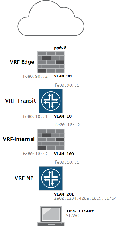
Notice that the client VLAN is the only segment with a globally routed IPv6 address. With IPv6, it is perfectly fine to use only link-local (non-routed) addressing on your transit networks, and in fact it has several benefits! If you’re curious what those benefits are, you can read all about it in RFC7407 by Eric Vyncke and Michael Behringer.
Addressing configuration
My provider has assigned me two static prefixes to me. These are not the real ones btw 🙂
IPv6 LAN prefix 	2a02:1234:420a::/48
IPv6 WAN prefix 	2a02:1234:8401:9a00::/64
First, let’s configure our WAN interface with a static IP address in the WAN range.
[edit]
admin@NPFW01# set interfaces pp0 unit 0 family inet6 address 2a02:1234:8401:9a00::1/64
As I’m using PPPoE, I will need to add a static default route (::/0) with the pp0.0 interface as next-hop. Also, I’m using VRFs so I need to add it under the right routing instance.
[edit routing-instances VRF-Edge]
admin@NPFW01# set routing-options rib VRF-Edge.inet6.0 static route ::/0 next-hop pp0.0
A quick ping to Google to verify that we have IPv6 connectivity on the external interface.
admin@NPFW01> ping inet6 2001:4860:4860::8888 routing-instance VRF-Edge source 2a02:1234:8401:9a00::1 rapid count 10
PING6(56=40+8+8 bytes) 2a02:1234:8401:9a00::1 --> 2001:4860:4860::8888
!!!!!!!!!!
--- 2001:4860:4860::8888 ping6 statistics ---
10 packets transmitted, 10 packets received, 0% packet loss
round-trip min/avg/max/std-dev = 30.980/31.647/32.716/0.444 ms
So far, so good. Let’s configure the internal interfaces now.
Configuration for the link-local addresses on the Firewall:
[edit interfaces ae0 unit 90 family inet6]
admin@NPFW01# show
address fe80:90::2/64;
[edit interfaces ae1 unit 10 family inet6]
admin@NPFW01# show
address fe80:10::2/64;
[edit interfaces ae1 unit 100 family inet6]
admin@NPFW01# show
address fe80:100::2/64;
And for the switch:
{master:0}[edit interfaces vlan unit 10 family inet6]
admin@NPSWC01# show
address fe80:10::1/64;
{master:0}[edit interfaces vlan unit 90 family inet6]
admin@NPSWC01# show
address fe80:90::1/64;
{master:0}[edit interfaces vlan unit 100 family inet6]
admin@NPSWC01# show
address fe80:100::1/64;
{master:0}[edit interfaces vlan unit 101 family inet6]
admin@NPSWC01# show
address fe80:101::1/64;
In my case, the interfaces are already in the right routing instances so I don’t need to add them anymore. Don’t forget this step though, if you are recreating this in your own lab.
After a commit, we can confirm reachability between the devices inside their routing instances.
admin@NPSWC01> ping fe80:90::2 routing-instance VRF-Transit source fe80:90::1 rapid count 5
PING6(56=40+8+8 bytes) fe80:90::1 --> fe80:90::2
!!!!!
--- fe80:90::2 ping6 statistics ---
5 packets transmitted, 5 packets received, 0% packet loss
round-trip min/avg/max/std-dev = 3.981/4.689/6.566/0.947 ms
admin@NPSWC01> ping fe80:10::2 routing-instance VRF-Transit source fe80:10::1 rapid count 5
PING6(56=40+8+8 bytes) fe80:10::1 --> fe80:10::2
!!!!!
--- fe80:10::2 ping6 statistics ---
5 packets transmitted, 5 packets received, 0% packet loss
round-trip min/avg/max/std-dev = 4.181/5.018/6.296/0.731 ms
admin@NPSWC01> ping fe80:100::2 routing-instance VRF-NP source fe80:100::1 rapid count 5
PING6(56=40+8+8 bytes) fe80:100::1 --> fe80:100::2
!!!!!
--- fe80:100::2 ping6 statistics ---
5 packets transmitted, 5 packets received, 0% packet loss
round-trip min/avg/max/std-dev = 3.924/4.819/5.715/0.575 ms
Both devices should now have an entry for eachother in the IPv6 neighbour tables, which is the equivalent of the v4 ARP table.
admin@NPSWC01> show ipv6 neighbors
IPv6 Address                 Linklayer Address  State       Exp Rtr Secure Interface
fe80:10::2                   a8:d0:e5:d3:2a:81  stale       927 yes no      vlan.10
fe80:90::2                   a8:d0:e5:d3:2a:80  stale       896 yes no      vlan.90
fe80:100::2                  a8:d0:e5:d3:2a:81  stale       887 yes no      vlan.100
Client network addressing
Last step is to assign the VLAN201 interface with a publically routed interface. I will be configuring this address: 2a02:1234:420a:10c9::1/64
There are probably more elegant addressing designs but this is what I came up with:
- The first 48 bits are our globally routed prefix.
- For the next 16 bits, I’ve used the leading 4 bits to represent the site number. This is my first site, so number 1.
- The last 12 bits represent the VLAN number in hexadecimal notation, as there are 4096 vlans available in the dot1q standard – VLAN201 is C9 in hex!
Granted, it’s not the most scalable solution, as it only gives me 15 more sites and it wastes a lot of addresses but hey, this is not a multinational yet! 🙂
Here’s the configuration for the VLAN201 SVI:
{master:0}[edit interfaces vlan unit 201 family inet6]
admin@NPSWC01# show
address 2a02:1234:420a:10c9::1/64;
Enabling Router Advertisements
To enable dynamic address assignments (SLAAC) for the clients behind it, we also need to enable router advertisements on this interface. The other-stateful-configuration command will add the O-Flag to the advertisements, so we can later add the additional DNS information via DHCPv6.
{master:0}[edit protocols router-advertisement interface vlan.201]
admin@NPSWC01# show
other-stateful-configuration;
prefix 2a02:1234:420a:10c9::/64;
}
After committing, the client has assigned itself an IPv6 based on the received router advertisements.
Ethernet adapter Ethernet:

   Connection-specific DNS Suffix  . : ***-networks.local
   IPv6 Address. . . . . . . . . . . : 2a02:1234:420a:10c9:b1d1:660c:ac69:c5f8
   Temporary IPv6 Address. . . . . . : 2a02:1234:420a:10c9:3c71:b6f2:e93f:67ab
   Link-local IPv6 Address . . . . . : fe80::b1d1:660c:ac69:c5f8%6
   IPv4 Address. . . . . . . . . . . : 10.255.1.13
   Subnet Mask . . . . . . . . . . . : 255.255.255.128
   Default Gateway . . . . . . . . . : fe80::5e45:27ff:fee7:af81%6
                                       10.255.1.1
The basics are now in place. Now we will add some routing to make this prefix reachable.
Configuring static routes
As mentioned, my EX2200 switches do not support OSPFv3 so static routing is the only option for now…
Note – If you are using link-local addresses as the next-hop, you must use the qualified-next-hop statement with the interface in question.
Static routes, using link-local addresses, added on the switch’s routing-instances:
{master:0}[edit routing-instances VRF-Transit routing-options]
admin@NPSWC01# show
rib VRF-Transit.inet6.0 {
    static {
        route ::/0 {
            qualified-next-hop fe80:90::2 {
                interface vlan.90;
            }
        }
        route 2a02:1234:420a:10c9::/64 {
            qualified-next-hop fe80:10::2 {
                interface vlan.10;
            }
        }
    }
}
{master:0}[edit routing-instances VRF-NP routing-options]
admin@NPSWC01# show
rib VRF-NP.inet6.0 {
    static {
        route ::/0 {
            qualified-next-hop fe80:100::2 {
                interface vlan.100;
            }
        }
    }
}
And the routes on the firewall:
[edit routing-instances VRF-Internal routing-options]
admin@NPFW01# show
rib VRF-Internal.inet6.0 {
    static {
        route ::/0 {
            qualified-next-hop fe80:10::1 {
                interface ae1.10;
            }
        }
        route 2a02:1234:420a:10c9::/64 {
            qualified-next-hop fe80:100::1 {
                interface ae1.100;
            }
        }
    }
}
admin@NPFW01# show
rib VRF-Edge.inet6.0 {
    static {
        route ::/0 next-hop pp0.0;
        route 2a02:1234:420a:10c9::/64 {
            qualified-next-hop fe80:90::1 {
                interface ae0.90;
            }
        }
    }
}
After adding this configuration, and assuming that the necessary firewall policies are in place, the client can now ping outbound to the internet.
C:\Users\user>ping 2001:4860:4860::8888

Pinging 2001:4860:4860::8888 with 32 bytes of data:
Reply from 2001:4860:4860::8888: time=30ms
Reply from 2001:4860:4860::8888: time=30ms
Reply from 2001:4860:4860::8888: time=31ms
Reply from 2001:4860:4860::8888: time=30ms

Ping statistics for 2001:4860:4860::8888:
    Packets: Sent = 4, Received = 4, Lost = 0 (0% loss),
Approximate round trip times in milli-seconds:
    Minimum = 30ms, Maximum = 31ms, Average = 30ms
That’s all it takes to implement static routing for IPv6, easy-peasy!