Up until now, I’ve been doing most of my studies on real hardware. This was okay with Cisco gear, but Juniper hardware isn’t as cheap on the second hand market. Second, I always loose vast amounts of time reconfiguring appliances on the console, cabling them up, reconfiguring switchports and installing physical or virtual test machines. I recently installed an ESXi whitebox, with loads of RAM and compute power idle, so why not start virtualizing my labs?
The Juniper vSRX Integrated Virtual Firewall, formerly known as Firefly Perimeter, is a virtual appliance that brings all the features of the SRX firewalls to your virtual layer. Even better, you can use the full-featured trial version of the appliance for 60 days. Perfect for labbing purposes!
In this post, I will go through the steps of setting up the virtual appliance and giving it a basic configuration. Below is the topology I will be implementing and using for some parts of my JNCIS-SEC studies. I haven’t found an “official” installation guide from Juniper -although I haven’t really looked either- but the below scenario works for me.
Downloading and importing the virtual machine
You can download a 60-day trial version of the vSRX on the Juniper site, although you will need to register for a Juniper account. Get it here!
I am using VMware ESXi 6.0 so in my case I chose the OVA template: junos-vsrx-12.1X47-D20.7-domestic.ova.
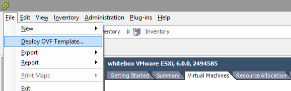
Once the file has been downloaded, start your vSphere Client and choose File > Deploy OVF Template
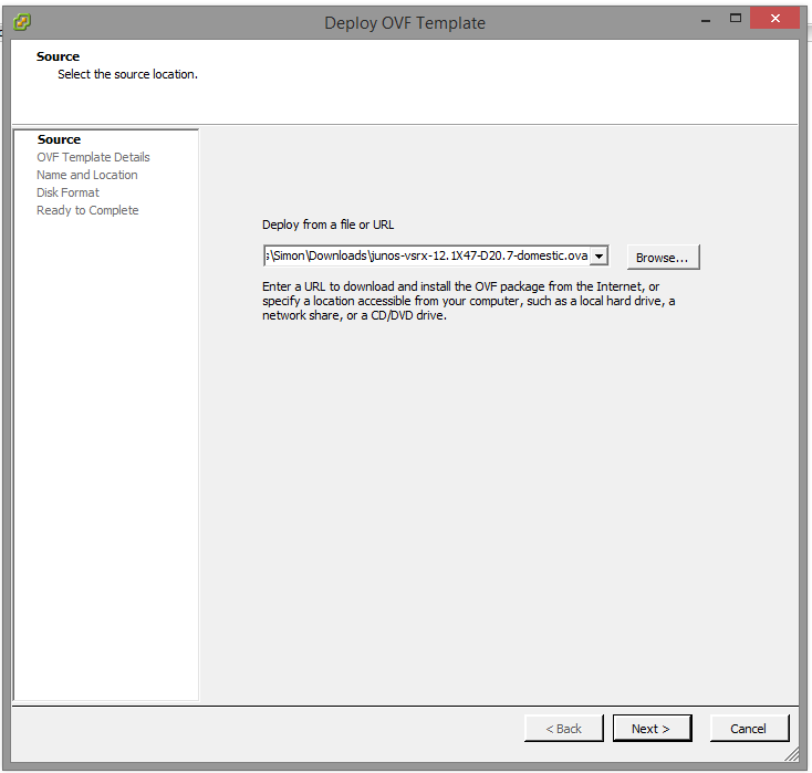
On the next window, enter the path for the OVA file you downloaded from the Juniper site earlier and click Next
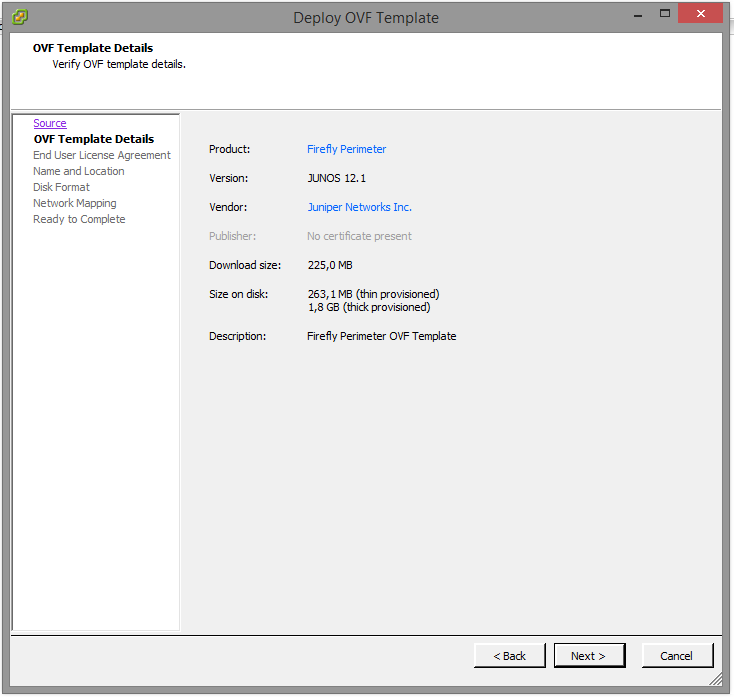
On the next screen, the vSphere client will give you an overview of the template properties.
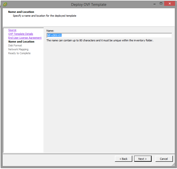
Click next and Accept the license agreement. On the next screen you can define a name for the Virtual Machine. I’m giving it the hostname of NP-vSRX-01
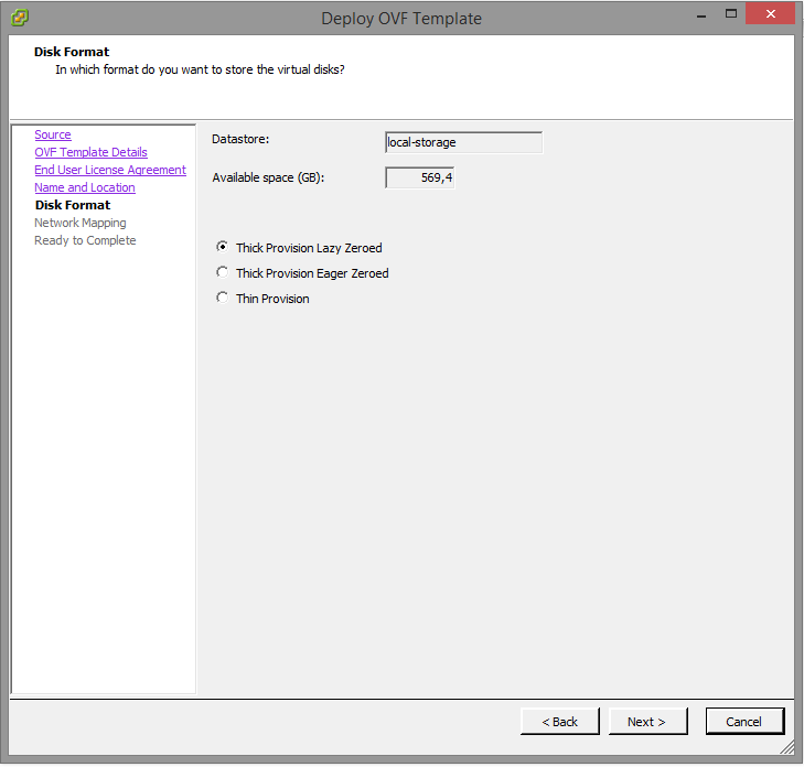
When vSphere asks you about the Disk Provisioning, choose Thick Provisioned – the default.
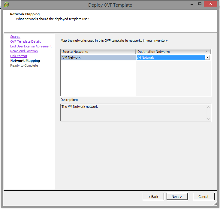
Leave the Network mappings at the defaults. We will manually assign the interfaces in the VM settings later.
When you arrive at the last page, the wizard will give you an overview of the settings you just entered. Don’t power on the device just yet, as we still need to add some interfaces.
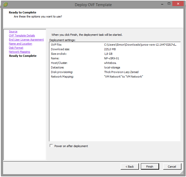
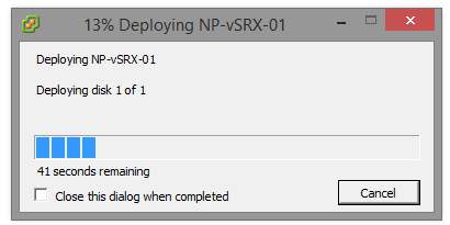
When you click Finish, vSphere will upload the image, set up the virtual machine and apply the settings.
Integrating vSRX into the topology
Before I start configuring the interfaces, let’s have a look at my lab topology.
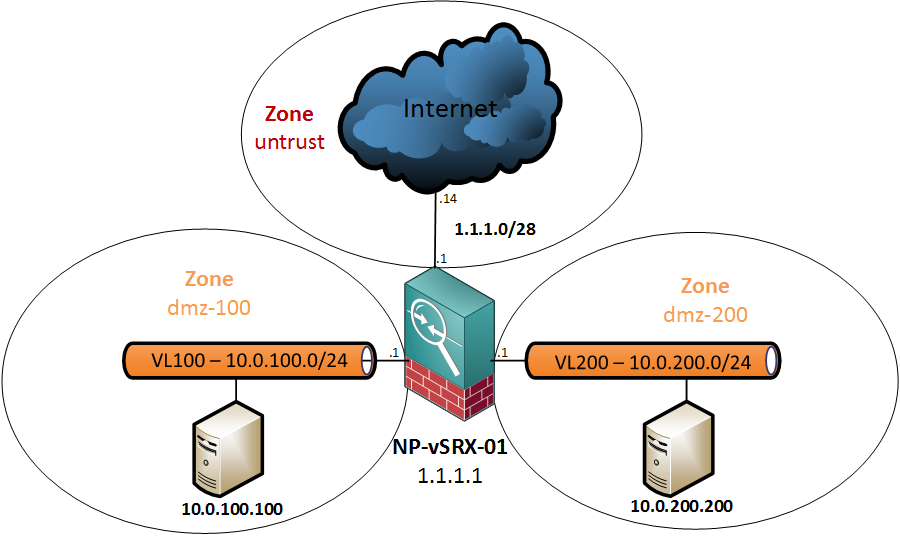
- The outside interface, in the untrust zone, will have an IP of 1.1.1.1/28. The next-hop for the default route will be 1.1.1.14, which is actually my hardware SRX. This network is tagged as VLAN255 towards my switches. I will use the 12 spare addresses for NAT labbing later on.
- On the inside, there are two networks with virtual machines, VLAN100 and VLAN200. These will both be in their own zone, dmz-100 and dmz-200.
To get this topology up and running, I will need three interfaces on the SRX. Here are my interface mappings:
Network Adapter 1 – ge0/0/0 – vlan255 (untrust)
Network Adapter 2 – ge0/0/1 – vlan100 (dmz-100)
Network Adapter 3 – ge0/0/2 – vlan200 (dmz-200)
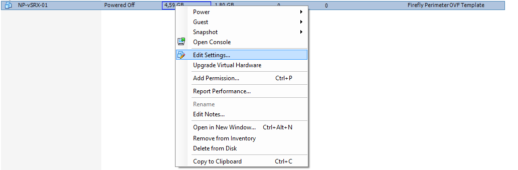
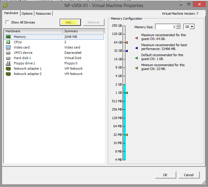
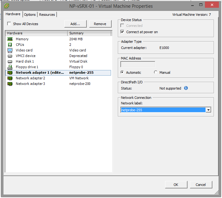
By default, the VM is provisioned with two interfaces. This would be your ge0/0/0 and ge0/0/1 interfaces. Let’s add a third one, which will be ge0/0/2. To do so, select the virtual machine, right-click and choose Edit settings. On the Settings window, click the Add button.
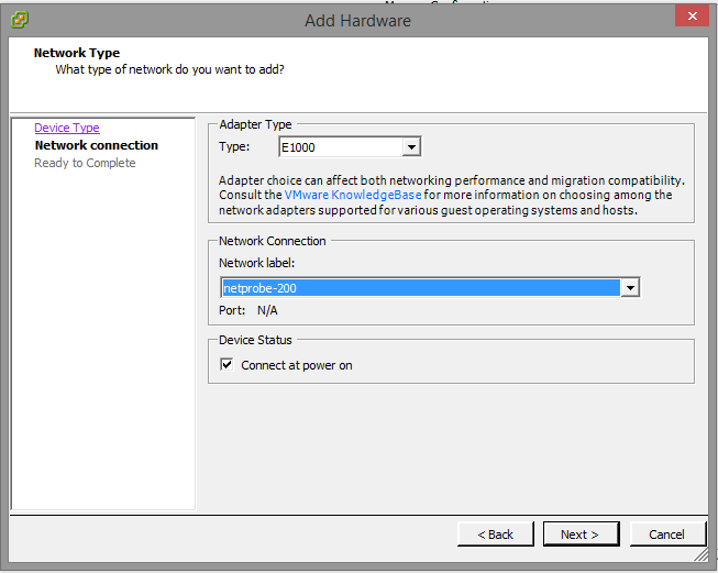
Choose Ethernet Adapter and click Next. On the next page, leave E1000 as the interface type. We can immediately map it to the correct VLAN (200) here.
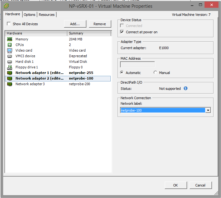
Click Next and Finish on the summary page. There are now three ethernet interfaces on the Machine Settings window.
Network Adapter 1 should be in VLAN255. This can be configured on the Network Label dropdown menu.
Repeat for Network Adapter 2, which should be in VLAN100.
Finally, after lots of clicking around, our machine is ready to go. Let’s power it up and open the Console to add the basic settings.
When the device has booted, you will be presented with the username prompt. As is the case with the hardware SRXs, you should enter root as the username, without a password.
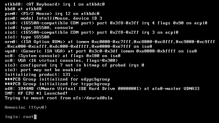
When you first log on as root, you are put in the BSD environment. Enter cli to get to the Junos command prompt.
In the operational command prompt, let’s verify that we have our ge0/0/0, ge0/0/1 and ge0/0/2 interfaces by entering the show interfaces terse command.
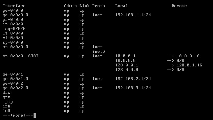
Excellent, our interfaces are there but as you can see they are preconfigured with standard IP addresses in the RFC1918 192.168.0.0/16 ranges. Let’s get rid of these factory-defaults and start with a clean slate. To do this, enter configuration mode and wipe all configuration by entering delete in the root context.
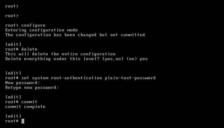
You will not be able to save the configuration without entering a root authentication password. That syntax is in the screenshot.
To get the outside connectivity, I added the interface and routing configuration below. Since this is a lab, and I’m connecting from the outside I’m allowing ping and SSH on the untrust zone
system {
    root-authentication {
        encrypted-password "$1$st4hY7Hd$jYp76UJZvKaQV09jcj72P1"; ## SECRET-DATA
    }
    services {
        ssh;
    }
}
interfaces {
    ge-0/0/0 {
        unit 0 {
            family inet {
                address 1.1.1.1/28;
            }
        }
    }
}
routing-options {
    static {
        route 0.0.0.0/0 next-hop 1.1.1.14;
    }
}
security {
    zones {
        security-zone untrust {
            host-inbound-traffic {
                system-services {
                    ssh;
                    ping;
                }
            }
            interfaces {
                ge-0/0/0.0;
            }
        }
    }
}
Once this config is active, I can SSH directly into the virtual device instead of configuring it on the console. Now, let’s configure the addressses for VLAN100 and VLAN200.
[edit interfaces]
root# show
ge-0/0/1 {
    unit 0 {
        family inet {
            address 10.0.100.1/24 {
                preferred;
            }
        }
    }
}
ge-0/0/2 {
    unit 0 {
        family inet {
            address 10.0.200.1/24 {
                preferred;
            }
        }
    }
}
Next up, configuring the security zones, dmz-100 and dmz-200
[edit security zones]
root# show
security-zone dmz-100 {
    host-inbound-traffic {
        system-services {
            ping;
        }
    }
    interfaces {
        ge-0/0/1.0;
    }
}
security-zone dmz-200 {
    host-inbound-traffic {
        system-services {
            ping;
        }
    }
    interfaces {
        ge-0/0/2.0;
    }
}
For testing purposes, I’m allowing ping inbound on the dmz interfaces. After committing, let’s try reaching the default gateway on the server in VLAN100.
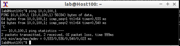
Great, it works! Now I have a fully functional, virtual topology for my JNCIS-SEC studies. No more messing around with cables! 🙂