Tag Archives: High-Availability

Virtual Chassis on EX2200 switches

The Juniper Virtual Chassis technology allows you to combine multiple physical switches into one logical switch stack, which reduces the management overhead of dealing with many switches. Because all members are acting as a single device, with a proprietary control protocol underneath, there is no need for Spanning Tree and its blocked links. It also has dual routing engine support, albeit with some feature limitations on the EX2200 platform.

Unlike the high-end Juniper switches, the EX2200 does not have dedicated virtual-chassis ports either, so you are limited to using the on-board ethernet ports. The cross-member bandwidth should be OK for basic access deployments though, so here’s how to set it up.

First, gather the serial numbers of all your switches. There are several commands that will show you the serial. I’ve used show chassis hardware

root> show chassis hardware
Hardware inventory:
Item             Version  Part number  Serial number     Description
Chassis                                CW0210160462      EX2200-24T-4G
Routing Engine 0 REV 11   750-026468   CW0210160462      EX2200-24T-4G
FPC 0            REV 11   750-026468   CW0210160462      EX2200-24T-4G
  CPU                     BUILTIN      BUILTIN           FPC CPU
  PIC 0                   BUILTIN      BUILTIN           24x 10/100/1000 Base-T
  PIC 1          REV 11   750-026468   CW0210160462      4x GE SFP
Power Supply 0                                           PS 100W AC
Fan Tray                                                 Fan Tray

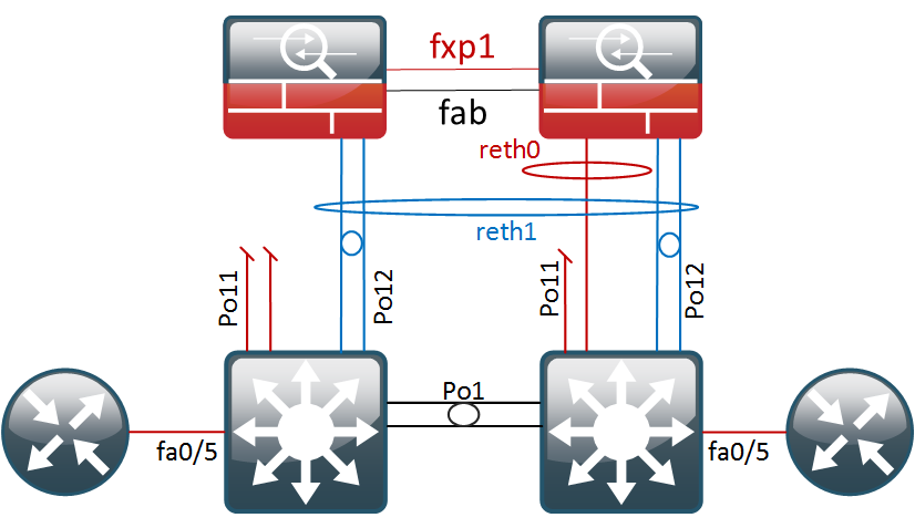
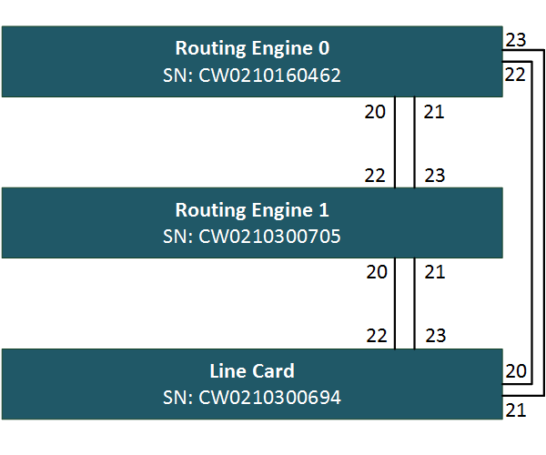
Do this for all your switches and copy them to notepad. You will need them later. Mine are indicated on the diagram below.

EX2200 Virtual Chassis Topology

Next, we need to configure our Ethernet ports for virtual-chassis functionality. The EX2200 does not have dedicated VCP ports so we need to convert some ethernet ports. As shown on the drawing, I will use the last four ports on each switch. To activate the ports for VC functionality, enter the following commands.

{master:0}
root> request virtual-chassis vc-port set pic-slot 0 port 20

{master:0}
root> request virtual-chassis vc-port set pic-slot 0 port 21

{master:0}
root> request virtual-chassis vc-port set pic-slot 0 port 22

{master:0}
root> request virtual-chassis vc-port set pic-slot 0 port 23

Rinse and repeat on switch two and three. You can verify the ports were added correctly to the virtual chassis with the following command.

root> show virtual-chassis vc-port
fpc0:
--------------------------------------------------------------------------
Interface   Type              Trunk  Status       Speed        Neighbor
or                             ID                 (mbps)       ID  Interface
PIC / Port
0/20        Configured         -1    Down         1000
0/21        Configured         -1    Down         1000
0/22        Configured         -1    Down         1000
0/23        Configured         -1    Down         1000

Before we can move on to connecting the cables, we have to set up the virtual chassis parameters on our primary routing engine.

We will set up the virtual-chassis in pre-provisioned mode, where we manually tie the serial ids to the member id. The first two switches will be configured as routing engines, one master and one backup, and the last switch will serve as a dumb old line-card. In my case, the virtual chassis configuration on routing engine 0 looks like this:

{master:0}[edit virtual-chassis]
root# show
preprovisioned;
member 0 {
    role routing-engine;
    serial-number CW0210160462;
}
member 1 {
    role routing-engine;
    serial-number CW0210300705;
}
member 2 {
    role line-card;
    serial-number CW0210300694;
}

Now that this is set up, I have connected the cables and the virtual chassis has formed. You can verify VC state and inter-switch connectivity using the show virtual-chassis status command.

root> show virtual-chassis status

Preprovisioned Virtual Chassis
Virtual Chassis ID: fd81.5b7b.172c
Virtual Chassis Mode: Enabled
                                           Mstr           Mixed Neighbor List
Member ID  Status   Serial No    Model     prio  Role      Mode ID  Interface
0 (FPC 0)  Prsnt    CW0210160462 ex2200-24t-4g 129 Master*   NA  1  vcp-255/0/20
                                                                 1  vcp-255/0/21
                                                                 2  vcp-255/0/22
                                                                 2  vcp-255/0/23
1 (FPC 1)  Prsnt    CW0210300705 ex2200-24t-4g 129 Backup    NA  2  vcp-255/0/20
                                                                 2  vcp-255/0/21
                                                                 0  vcp-255/0/22
                                                                 0  vcp-255/0/23
2 (FPC 2)  Prsnt    CW0210300694 ex2200-24t-4g   0 Linecard  NA  0  vcp-255/0/20
                                                                 0  vcp-255/0/21
                                                                 1  vcp-255/0/22
                                                                 1  vcp-255/0/23

This command shows us the IDs, serials and roles of all the members. The far-right columns also show on which ports the neighbours are detected. You can use this to verify everything is properly cabled up.

A quick terse command also shows us all interfaces in the stack are available, except for the ones we dedicated as VCP ports.

root> show interfaces terse | no-more
Interface               Admin Link Proto    Local                 Remote
vcp-255/0/20            up    up
vcp-255/0/20.32768      up    up
vcp-255/0/21            up    up
vcp-255/0/21.32768      up    up
vcp-255/0/22            up    up
vcp-255/0/22.32768      up    up
vcp-255/0/23            up    up
vcp-255/0/23.32768      up    up
ge-0/0/0                up    down
ge-0/0/0.0              up    down eth-switch
ge-0/0/1                up    down
ge-0/0/1.0              up    down eth-switch
ge-0/0/2                up    down
ge-0/0/2.0              up    down eth-switch
ge-0/0/3                up    down
ge-0/0/3.0              up    down eth-switch
ge-0/0/4                up    down
ge-0/0/4.0              up    down eth-switch
ge-0/0/5                up    down
ge-0/0/5.0              up    down eth-switch
ge-0/0/6                up    down
ge-0/0/6.0              up    down eth-switch
ge-0/0/7                up    down
ge-0/0/7.0              up    down eth-switch
ge-0/0/8                up    down
ge-0/0/8.0              up    down eth-switch
ge-0/0/9                up    down
ge-0/0/9.0              up    down eth-switch
ge-0/0/10               up    down
ge-0/0/10.0             up    down eth-switch
ge-0/0/11               up    down
ge-0/0/11.0             up    down eth-switch
ge-0/0/12               up    down
ge-0/0/12.0             up    down eth-switch
ge-0/0/13               up    down
ge-0/0/13.0             up    down eth-switch
ge-0/0/14               up    down
ge-0/0/14.0             up    down eth-switch
ge-0/0/15               up    down
ge-0/0/15.0             up    down eth-switch
ge-0/0/16               up    down
ge-0/0/16.0             up    down eth-switch
ge-0/0/17               up    down
ge-0/0/17.0             up    down eth-switch
ge-0/0/18               up    down
ge-0/0/18.0             up    down eth-switch
ge-0/0/19               up    down
ge-0/0/19.0             up    down eth-switch
ge-1/0/0                up    down
ge-1/0/0.0              up    down eth-switch
ge-1/0/1                up    down
ge-1/0/1.0              up    down eth-switch
ge-1/0/2                up    down
ge-1/0/2.0              up    down eth-switch
ge-1/0/3                up    down
ge-1/0/3.0              up    down eth-switch
ge-1/0/4                up    down
ge-1/0/4.0              up    down eth-switch
ge-1/0/5                up    down
ge-1/0/5.0              up    down eth-switch
ge-1/0/6                up    down
ge-1/0/6.0              up    down eth-switch
ge-1/0/7                up    down
ge-1/0/7.0              up    down eth-switch
ge-1/0/8                up    down
ge-1/0/8.0              up    down eth-switch
ge-1/0/9                up    down
ge-1/0/9.0              up    down eth-switch
ge-1/0/10               up    down
ge-1/0/10.0             up    down eth-switch
ge-1/0/11               up    down
ge-1/0/11.0             up    down eth-switch
ge-1/0/12               up    down
ge-1/0/12.0             up    down eth-switch
ge-1/0/13               up    down
ge-1/0/13.0             up    down eth-switch
ge-1/0/14               up    down
ge-1/0/14.0             up    down eth-switch
ge-1/0/15               up    down
ge-1/0/15.0             up    down eth-switch
ge-1/0/16               up    down
ge-1/0/16.0             up    down eth-switch
ge-1/0/17               up    down
ge-1/0/17.0             up    down eth-switch
ge-1/0/18               up    down
ge-1/0/18.0             up    down eth-switch
ge-1/0/19               up    down
ge-1/0/19.0             up    down eth-switch
ge-2/0/0                up    down
ge-2/0/0.0              up    down eth-switch
ge-2/0/1                up    down
ge-2/0/1.0              up    down eth-switch
ge-2/0/2                up    down
ge-2/0/2.0              up    down eth-switch
ge-2/0/3                up    down
ge-2/0/3.0              up    down eth-switch
ge-2/0/4                up    down
ge-2/0/4.0              up    down eth-switch
ge-2/0/5                up    down
ge-2/0/5.0              up    down eth-switch
ge-2/0/6                up    down
ge-2/0/6.0              up    down eth-switch
ge-2/0/7                up    down
ge-2/0/7.0              up    down eth-switch
ge-2/0/8                up    up
ge-2/0/8.0              up    up   eth-switch
ge-2/0/9                up    down
ge-2/0/9.0              up    down eth-switch
ge-2/0/10               up    down
ge-2/0/10.0             up    down eth-switch
ge-2/0/11               up    down
ge-2/0/11.0             up    down eth-switch
ge-2/0/12               up    down
ge-2/0/12.0             up    down eth-switch
ge-2/0/13               up    down
ge-2/0/13.0             up    down eth-switch
ge-2/0/14               up    down
ge-2/0/14.0             up    down eth-switch
ge-2/0/15               up    down
ge-2/0/15.0             up    down eth-switch
ge-2/0/16               up    down
ge-2/0/16.0             up    down eth-switch
ge-2/0/17               up    down
ge-2/0/17.0             up    down eth-switch
ge-2/0/18               up    down
ge-2/0/18.0             up    down eth-switch
ge-2/0/19               up    down
ge-2/0/19.0             up    down eth-switch
bme0                    up    up
bme0.32768              up    up   inet     128.0.0.1/2
                                            128.0.0.16/2
                                            128.0.0.32/2
                                   tnp      0x10
bme0.32770              down  up   eth-switch
bme0.32771              down  up   eth-switch
dsc                     up    up
gre                     up    up
ipip                    up    up
lo0                     up    up
lo0.16384               up    up   inet     127.0.0.1           --> 0/0
lsi                     up    up
me0                     up    down
me0.0                   up    down inet
mtun                    up    up
pimd                    up    up
pime                    up    up
tap                     up    up
vlan                    up    up
vlan.0                  up    up   inet     192.168.1.1/24
vme                     up    down

We can login to other chassis member for troubleshooting by using the following command. When you log in to a line card JunOS will alert you that it shouldn’t be used for configuration.

root> request session member 2

--- JUNOS 12.3R11.2 built 2015-09-24 11:14:53 UTC
root@:LC:2%
root@:LC:2% cli
warning: This chassis is operating in a non-master role as part of a virtual-chassis (VC) system.
warning: Use of interactive commands should be limited to debugging and VC Port operations.
warning: Full CLI access is provided by the Virtual Chassis Master (VC-M) chassis.
warning: The VC-M can be identified through the show virtual-chassis status command executed at this console.
warning: Please logout and log into the VC-M to use CLI.
{linecard:2}
root>

The out of band management interface, on the back of the switches, can use the same shared IP address across all VC members. To do so, you need to configure the vme interface with the desired management IP. In the background, all member’s management ports (otherwise known as me interfaces) are added to a special management VLAN which is tied to the layer3 vme interface.

{master:0}[edit interfaces]
root# show vme
unit 0 {
    family inet {
        address 10.6.66.25/24;
    }
}

All physical management interfaces can be connected to the OOB management VLAN, and the virtual chassis can respond to ARP requests on all of them.

Note – the VME interface will not work if you already have conflicting configuration on the me interface.

Because we have two routing engines, it’s also recommended to configure the commit synchronize option. When the configuration is committed on the primary routing engine, it will copy over to the backup routing engine. Both routing engines will then validate and activate the new configuration during the commit operation.

{master:0}[edit]
root# set system commit synchronize

Under the hood, the switches are running VCCP, a Juniper proprietary protocol largely based on IS-IS. If you’re interested, you can verify much of the protocol state from the command line, but I won’t go into detail.

root> show virtual-chassis protocol ?
Possible completions:
  adjacency            Show virtual chassis adjacency database
  database             Show virtual chassis link-state database
  interface            Show virtual chassis protocol interface information
  route                Show virtual chassis routing table
  statistics           Show virtual chassis performance statistics

Quoting Juniper here, “most high availability features, including Graceful Routing Engine switchover (GRES), Nonstop bridging (NSB), Nonstop active routing (NSR), and Nonstop software upgrade (NSSU), are not supported on an EX2200 Virtual Chassis.” Therefore, I would not rely an EX2200 virtual chassis as a core switch HA solution.. It does make sense using EX2200 virtual chassis in the access layer though, for simplified management and cross-switch etherchannel connectivity.

Removing Virtual-Chassis Configuration

A switch that was previously member of a virtual chassis may give you some headache when you’re trying to use it as a standard switch again. For example, VC ports can not be returned to their original state, or you might see that it stays in the previous role, even though you’ve removed the configuration. Here’s what seems to work for me.

If you haven’t done so, delete all virtual-chassis configuration

{linecard:2}[edit]
root# delete virtual-chassis
root# commit
warning: Could not connect to fpc0 : Can't assign requested address
warning: Cannot connect to other RE, ignoring it
commit complete

Go into shell mode (start shell) and delete all virtual chassis configuration files.

root@:LC:0% cd /config/vchassis/
root@:LC:0% ls
vc.db                   vc.tlv.db.0             vclocal.conf.tlv
vc.param                vc.tlv.db.1             vclocal.conf.tlv.0
vc.tlv.db               vclocal.conf            vclocal.conf.tlv.1
root@:LC:0% rm *.*

Then, return to operational mode with the cli command and do a system reboot to flush all stale virtual-chassis configuration from memory.

After the reboot, the switch will be in the default state again

Amnesiac (ttyu0)

login: root
Password:

--- JUNOS 12.3R11.2 built 2015-09-24 11:14:53 UTC
root@:RE:0% cli
{master:0}
root> show virtual-chassis

Virtual Chassis ID: 7c29.6cd0.a3b3
Virtual Chassis Mode: Enabled
                                           Mstr           Mixed Neighbor List
Member ID  Status   Serial No    Model     prio  Role      Mode ID  Interface
0 (FPC 0)  Prsnt    CW0210300694 ex2200-24t-4g 128 Master*   NA

Member ID for next new member: 1 (FPC 1)

{master:0}
root> show virtual-chassis vc-port
fpc0:
--------------------------------------------------------------------------

{master:0}

Any questions or comments? Feel free to add them below!

Juniper SRX Clustering with LACP

Most deployment guides for SRX clusters out there focus on standard two-port deployments, where you have one port in, one port out and a couple of cluster links that interconnect and control the cluster. Unfortunately, in that design, one simple link failure will usually make the cluster fail over. Coming from the R&S realm, I am very careful when it comes to physical redundancy so I wanted to figure out a way to get this working with Etherchannels.

After a lot of reading and some trial and error, I ended up with a working solution. Probably not perfect, but definitely more redundant. So, in this post we will get the topology below configured and afterwards do some failover testing.

Physical connections

Basic Cluster Setup

The commands below will get the basic cluster up and running, assuming you have already configured the cluster and node ids.

set system root-authentication encrypted-password "$1$FQl4d.NC$l25c0bDGr5aPq9ZHx0R.S."
set groups node0 system host-name FW01A
set groups node1 system host-name FW01B
set apply-groups "${node}"
set chassis cluster reth-count 2
set chassis cluster redundancy-group 0 node 0 priority 120
set chassis cluster redundancy-group 0 node 1 priority 1
set chassis cluster redundancy-group 1 node 0 priority 120
set chassis cluster redundancy-group 1 node 1 priority 1
set chassis cluster redundancy-group 1 preempt
set interfaces fab0 fabric-options member-interfaces fe-0/0/5
set interfaces fab1 fabric-options member-interfaces fe-1/0/5

Layer3 Etherchannel configuration on the SRX

The physical ports will be bundled in two reth interface. Per reth interface, we will add two physical ports per cluster node, which yields a total of four ports. However only two links will ever be actively forwarding traffic – those on the active RG.

Physical connections

It is important that the links from every cluster nodes are terminated on separate etherchannels on the switches. Otherwise the switches would also load-balance the traffic over the two non-forwarding ports, as documented here…
In my topology, both switches have a Port-Channel 11 and 12, going to their own cluster node.

{primary:node0}
root@FW01A> show configuration interfaces
fe-0/0/0 {
    fastether-options {
        redundant-parent reth0;
    }
}
fe-0/0/1 {
    fastether-options {
        redundant-parent reth0;
    }
}
fe-0/0/2 {
    fastether-options {
        redundant-parent reth1;
    }
}
fe-0/0/3 {
    fastether-options {
        redundant-parent reth1;
    }
}
fe-1/0/0 {
    fastether-options {
        redundant-parent reth0;
    }
}
fe-1/0/1 {
    fastether-options {
        redundant-parent reth0;
    }
}
fe-1/0/2 {
    fastether-options {
        redundant-parent reth1;
    }
}
fe-1/0/3 {
    fastether-options {
        redundant-parent reth1;
    }
}

Pay special attention to the configuration of the reth interfaces. First, we tie the redundant interfaces to our redundancy-group 1, in which we will later control the failover conditions.

The minimum-links command determines how many interfaces must be up before the LACP bundle is considered up. Although we have two interfaces per cluster, we still want traffic forwarded in a worst-case scenario. Setting minimum-links 1 will keep the Etherchannel up even in the unlikely event of having three physical ports down.

reth0 {
    vlan-tagging;
    redundant-ether-options {
        redundancy-group 1;
        minimum-links 1;
        lacp {
            active;
            periodic fast;
        }
    }
    unit 111 {
        vlan-id 111;
        family inet {
            address 1.1.1.1/28;
        }
    }
}
reth1 {
    vlan-tagging;
    redundant-ether-options {
        redundancy-group 1;
        minimum-links 1;
        lacp {
            active;
            periodic fast;
        }
    }
    unit 255 {
        vlan-id 255;
        family inet {
            address 10.255.255.254/28;
        }
    }
}

By adding the vlan-tagging command, and adding a logical subinterface (unit 255) with vlan-id 255 specified, we are creating a tagged L3 Etherchannel. In other words, the SRX is expecting packets for sub-interface reth1.255 to be tagged with a dot1q value of 255. The unit number can be any number you like, but it’s best to keep the unit number and the dot1q value aligned – for your own sanity! 🙂

Security Zones and Policies

To check basic connectivity and later run some failover tests, I have added the following configuration for the Security Zones, Policies and Source NAT. In a production environment, you probably won’t be allowing ping.

root@FW01A# show zones
security-zone trust {
    address-book {
        address Net-10.255.255.240-28 10.255.255.240/28;
    }
    host-inbound-traffic {
        system-services {
            ping;
        }
    }
    interfaces {
        reth1.255;
    }
}
security-zone untrust {
    address-book {
        address Net-1.1.1.0-28 1.1.1.0/28;
    }
    interfaces {
        reth0.111 {
            host-inbound-traffic {
                system-services {
                    ping;
                }
            }
        }
    }
}
{primary:node0}[edit security]
root@FW01A# show policies
from-zone trust to-zone untrust {
    policy Test-Policy {
        match {
            source-address Net-10.255.255.240-28;
            destination-address Net-1.1.1.0-28;
            application any;
        }
        then {
            permit;
        }
    }
}
{primary:node0}[edit security]
root@FW01A# show nat
source {
    rule-set SNAT-Trust-to-Untrust {
        from zone trust;
        to zone untrust;
        rule HideNAT-1 {
            match {
                source-address 10.255.255.240/28;
            }
            then {
                source-nat {
                    interface;
                }
            }
        }
    }
}

Preparing the switches for L2

I’m running two Cisco 3550 switches as my layer3 core switches. For now, I will just add the Layer 1 and 2 stuff.

vlan 111
 name untrust
!
vlan 255
 name transit


interface range fastEthernet 0/1 - 2
 channel-group 11 mode active

interface range fastEthernet 0/3 - 4
 channel-group 12 mode active

int po 11
 switchport trunk encapsulation dot1q
 switchport mode trunk
 switchport nonegotiate
 switchport trunk allowed vlan 111

int po 12
 switchport mode trunk
 switchport nonegotiate
 switchport trunk allowed vlan 255

For CS2, we can copy paste the exact same config.

A second trunk link is added between the core switches, which will carry inter-switch traffic for VLAN 111 and 255.

interface FastEthernet0/23
 channel-group 1 mode active
!
interface FastEthernet0/24
 channel-group 1 mode active

...

interface Port-channel1
 switchport trunk encapsulation dot1q
 switchport trunk allowed vlan 111,255
 switchport mode trunk
 switchport nonegotiate

The LACP configuration is now complete, and after cabling everything up we see the Port-channels are in the bundled state:

NP-CS1>show etherchannel summary
Flags:  D - down        P - bundled in port-channel
        I - stand-alone s - suspended
        H - Hot-standby (LACP only)
        R - Layer3      S - Layer2
        U - in use      f - failed to allocate aggregator

        M - not in use, minimum links not met
        u - unsuitable for bundling
        w - waiting to be aggregated
        d - default port


Number of channel-groups in use: 3
Number of aggregators:           3

Group  Port-channel  Protocol    Ports
------+-------------+-----------+-----------------------------------------------
1      Po1(SU)         LACP      Fa0/23(P)   Fa0/24(P)
11     Po11(SU)        LACP      Fa0/1(P)    Fa0/2(P)
12     Po12(SU)        LACP      Fa0/3(P)    Fa0/4(P)

The SRX is bit more detailed with the information in the lacp command

root@FW01A> show lacp interfaces
Aggregated interface: reth0
    LACP state:       Role   Exp   Def  Dist  Col  Syn  Aggr  Timeout  Activity
      fe-0/0/0       Actor    No    No   Yes  Yes  Yes   Yes     Fast    Active
      fe-0/0/0     Partner    No    No   Yes  Yes  Yes   Yes     Slow    Active
      fe-0/0/1       Actor    No    No   Yes  Yes  Yes   Yes     Fast    Active
      fe-0/0/1     Partner    No    No   Yes  Yes  Yes   Yes     Slow    Active
      fe-1/0/0       Actor    No    No   Yes  Yes  Yes   Yes     Fast    Active
      fe-1/0/0     Partner    No    No   Yes  Yes  Yes   Yes     Slow    Active
      fe-1/0/1       Actor    No    No   Yes  Yes  Yes   Yes     Fast    Active
      fe-1/0/1     Partner    No    No   Yes  Yes  Yes   Yes     Slow    Active
    LACP protocol:        Receive State  Transmit State          Mux State
      fe-0/0/0                  Current   Slow periodic Collecting distributing
      fe-0/0/1                  Current   Slow periodic Collecting distributing
      fe-1/0/0                  Current   Slow periodic Collecting distributing
      fe-1/0/1                  Current   Slow periodic Collecting distributing

Layer3 Switch Configuration

Now that we have our layer 2 connectivity, we can move on to the IP addressing. On the L3 switches, I will configure the SVIs in the transit network, and run HSRP between them with hello/hold timers of 1 and 3 seconds. This would allow for a reasonable failover time in case of an outage.

NP-CS1:

interface Vlan255
 ip address 10.255.255.242 255.255.255.240
 standby 255 ip 10.255.255.241
 standby 255 timers 1 3
 standby 255 priority 110
 standby 255 preempt

NP-CS2:

NP-CS2#sh run int vlan 255
!
interface Vlan255
 ip address 10.255.255.243 255.255.255.240
 standby 255 ip 10.255.255.241
 standby 255 timers 1 3
 standby 255 preempt

The VLAN interfaces come up immediately and as a final test for basic L3 connectivity, we try pinging the SRX from the core switch.

NP-CS1#ping 10.255.255.254 repeat 10

Type escape sequence to abort.
Sending 10, 100-byte ICMP Echos to 10.255.255.254, timeout is 2 seconds:
!!!!!!!!!!
Success rate is 100 percent (10/10), round-trip min/avg/max = 1/2/4 ms

Checking the ARP table, we can see the Cluster MAC address, with the 4th last digit (1) being the cluster ID and the last two (01) the reth number.

NP-CS1#show ip arp
Protocol  Address          Age (min)  Hardware Addr   Type   Interface
Internet  10.255.255.254          1   0010.dbff.1001  ARPA   Vlan255
Internet  10.255.255.242          -   0012.7f81.8f00  ARPA   Vlan255
Internet  10.255.255.243          8   000d.ed6f.9680  ARPA   Vlan255
Internet  10.255.255.241          -   0000.0c07.acff  ARPA   Vlan255

The default route on both core switches is pointed to 10.255.255.254

ip route 0.0.0.0 0.0.0.0 10.255.255.254

Internet segment configuration

I have connected two routers to the fa0/5 interfaces of the switches and added them to vlan 111. They are running HSRP with a VIP of 1.1.1.14 and hello/hold timers of 1 and 3 seconds.

ISP1#show standby brief
                     P indicates configured to preempt.
                     |
Interface   Grp  Pri P State   Active          Standby         Virtual IP
Fa0/1       111  110   Active  local           1.1.1.13        1.1.1.14

Running a simple ping to test connectivity between the firewalls and the ISP router.

root@FW01A> ping 1.1.1.14 count 1
PING 1.1.1.14 (1.1.1.14): 56 data bytes
64 bytes from 1.1.1.14: icmp_seq=0 ttl=255 time=2.981 ms

*snip*

To test if traffic is being forwarded across the firewall, we finally try reaching the ISP routers from the core switches.

NP-CS1#ping 1.1.1.14 source vlan 255

Type escape sequence to abort.
Sending 5, 100-byte ICMP Echos to 1.1.1.14, timeout is 2 seconds:
Packet sent with a source address of 10.255.255.242
!!!!!
Success rate is 100 percent (5/5), round-trip min/avg/max = 1/2/4 ms

After many bits of configuration, our cluster is live so we can start implementing some failover mechanisms.

Configuring the interface-monitor

When the interface-monitor is configured, it sets a threshold value of 255 to each redundancy group. Each interface is assigned a custom weight for the redundancy group, which is detracted from the threshold if the interface goes physically down. When the threshold reaches zero, the redundancy group and all its objects fail over.

Note – a commmon mistake (trust me) is to mix up the interface monitor weights with the RG priorities. These are two separate values, the interface monitor threshold is always 255 by default.

In my lab scenario, I will give each port a value of 128. Two physical links down will trigger a failover to node 1. This is the final configuration for redundancy group 1:

{primary:node0}[edit chassis cluster]
root@FW01A# show
reth-count 2;
redundancy-group 0 {
    node 0 priority 120;
    node 1 priority 1;
}
redundancy-group 1 {
    node 0 priority 120;
    node 1 priority 1;
    preempt;
    interface-monitor {
        fe-0/0/0 weight 128;
        fe-0/0/1 weight 128;
        fe-1/0/0 weight 128;
        fe-1/0/1 weight 128;
        fe-0/0/2 weight 128;
        fe-0/0/3 weight 128;
        fe-1/0/3 weight 128;
        fe-1/0/2 weight 128;
    }

Failover scenarios

  • First, we will physically disconnect fe-0/0/0 which should not impact our regular traffic flow.

Disconnecting fe-0/0/0/

{primary:node0}
root@FW01A> show interfaces terse | match fe-0/0/0
fe-0/0/0                up    down
fe-0/0/0.111            up    down aenet    --> reth0.111
fe-0/0/0.32767          up    down aenet    --> reth0.32767

The JSRPD daemon logged the following entries in which we can see it decrement the value of 128 of the global threshold of 255.

root@FW01A> show log jsrpd | last | match 19:30
Oct  6 19:30:31 Interface fe-0/0/0 is going down
Oct  6 19:30:31 fe-0/0/0 interface monitored by RG-1 changed state from Up to Down
Oct  6 19:30:31 intf failed, computed-weight -128
Oct  6 19:30:31 LED changed from Green to Amber, reason is Monitored objects are down
Oct  6 19:30:31 Current threshold for rg-1 is 127. Failures: interface-monitoring
Oct  6 19:30:42 printing fpc_num h0
Oct  6 19:30:42 jsrpd_ifd_msg_handler: Interface reth0 is up
Oct  6 19:30:42 reth0 from  jsrpd_ssam_reth_read reth_rg_id=1

The chassis cluster interfaces also shows us the interface as down and how much weight it had:

root@FW01A> show chassis cluster interfaces | find Monitoring
Interface Monitoring:
    Interface         Weight    Status    Redundancy-group
    fe-1/0/2          128       Up        1
    fe-1/0/3          128       Up        1
    fe-0/0/3          128       Up        1
    fe-0/0/2          128       Up        1
    fe-1/0/1          128       Up        1
    fe-1/0/0          128       Up        1
    fe-0/0/1          128       Up        1
    fe-0/0/0          128       Down      1

Because our threshold value is still at 127 (255 – 128), RG1 is still active on node0 and no failover event was triggered.

Redundancy group: 1 , Failover count: 0
    node0                   120         primary        yes      no
    node1                   1           secondary      yes      no
  • As a second test, we will also unplug fe-0/0/1. Without the interface monitoring, this would halt the forwarding of traffic to the untrust zone as reth0 would have no more interfaces on node0.

Disconnecting fe-0/0/1 as well

To get a basic idea of the failover time, I’m running a ping test from the core switch.

Sending 1000, 100-byte ICMP Echos to 1.1.1.14, timeout is 2 seconds:
!!!!!!!!!!!!!!!!!!!!!!!!!!!!!!!!!!!!!!!!!!!!!!!!!!!!!!!!!!!!!!!!!!!!!!
!.!!!!!!!!!!!!!!!!!!!!!!!!!!!!!!!!!!!!!!!!!!!!!!!!!!!!!!!!!!!!!!!!!!!!
!!!!!!!!!!!!!!!!!!!!!!!!!!!!!!!!!!!!!!!!!!!!!!!!!!!!!!!!!!!!!!!!!!!!!!
*snip*

We lost one packet during the failover with a timeout of two seconds, which is not bad at all. The switchover is stateful so TCP connections should be able to handle this just fine. Let’s see what happened on the SRX…

Our interface monitor shows two interfaces down that had a weight of 128. The threshold should now have reached zero which retired node0 from the cluster.

root@FW01A> show chassis cluster interfaces | find Monitoring
Interface Monitoring:
    Interface         Weight    Status    Redundancy-group
    fe-1/0/2          128       Up        1
    fe-1/0/3          128       Up        1
    fe-0/0/3          128       Up        1
    fe-0/0/2          128       Up        1
    fe-1/0/1          128       Up        1
    fe-1/0/0          128       Up        1
    fe-0/0/1          128       Down      1
    fe-0/0/0          128       Down      1

Redundancy group 1 is now primary on node1. The routing engine is still active on node0.

root@FW01A> show chassis cluster status
Cluster ID: 1
Node                  Priority          Status    Preempt  Manual failover

Redundancy group: 0 , Failover count: 0
    node0                   120         primary        no       no
    node1                   1           secondary      no       no

Redundancy group: 1 , Failover count: 1
    node0                   0           secondary      yes      no
    node1                   1           primary        yes      no

And the JSRPD logged documented the entire event:

Oct  6 19:43:01 Interface fe-0/0/1 is going down
Oct  6 19:43:01 fe-0/0/1 interface monitored by RG-1 changed state from Up to Down
Oct  6 19:43:01 intf failed, computed-weight -256
Oct  6 19:43:01 RG(1) priority changed on node0 120->0 Priority is set to 0, Monitoring objects are down
Oct  6 19:43:01 Successfully sent an snmp-trap due to priority change from 120 to 0 on RG-1 on cluster 1 node 0. Reason: Priority is set to 0, Monitoring objects are down
Oct  6 19:43:01 Current threshold for rg-1 is -1. Setting priority to 0. Failures: interface-monitoring
Oct  6 19:43:01 Both the nodes are primary. RG-1 PRIMARY->SECONDARY_HOLD due to preempt/yield, my priority 0 is worse than other node's priority 1
Oct  6 19:43:01 Successfully sent an snmp-trap due to a failover from primary to secondary-hold on RG-1 on cluster 1 node 0. Reason: Monitor failed: IF
Oct  6 19:43:01 updated rg_info for RG-1 with failover-cnt 1 state: secondary-hold into ssam. Result = success, error: 0
Oct  6 19:43:01 reth0 ifd state changed from node0-primary -> node1-primary for RG-1
Oct  6 19:43:01 reth1 ifd state changed from node0-primary -> node1-primary for RG-1
Oct  6 19:43:01 updating primary-node as node1 for RG-1 into ssam. Previous primary was node0. Result = success, 0
Oct  6 19:43:01 Successfully sent an snmp-trap due to a failover from primary to secondary-hold on RG-1 on cluster 1 node 0. Reason: Monitor failed: IF
Oct  6 19:43:01 printing fpc_num h0
Oct  6 19:43:01 jsrpd_ifd_msg_handler: Interface reth0 is up
Oct  6 19:43:01 reth0 from  jsrpd_ssam_reth_read reth_rg_id=1
Oct  6 19:43:01 printing fpc_num h1
Oct  6 19:43:01 jsrpd_ifd_msg_handler: Interface reth1 is up
Oct  6 19:43:01 reth1 from  jsrpd_ssam_reth_read reth_rg_id=1
Oct  6 19:43:02 SECONDARY_HOLD->SECONDARY due to back to back failover timer expiry for RG-1
Oct  6 19:43:02 Successfully sent an snmp-trap due to a failover from secondary-hold to secondary on RG-1 on cluster 1 node 0. Reason: Back to back failover interval expired
Oct  6 19:43:02 updated rg_info for RG-1 with failover-cnt 1 state: secondary into ssam. Result = success, error: 0
Oct  6 19:43:02 Successfully sent an snmp-trap due to a failover from secondary-hold to secondary on RG-1 on cluster 1 node 0. Reason: Back to back failover interval expired

What is interesting is that the SRX is explicitly sending an SNMP trap for these events, so make sure you have a good monitoring tool and trap receiver in place, preferably with alerting.

  • As the ultimate test, I will unplug interface fe-1/0/0, the first port of node1, which will make the whole LACP bundle reth0 run on just one link. If we had configured minimum-links 2 this action would bring down the whole reth bundle

We are riding on one wheel now!

After pulling the cable, reth0 is strolling along on just one link:

root@FW01A> show lacp interfaces reth0 | find protocol
    LACP protocol:        Receive State  Transmit State          Mux State
      fe-0/0/0            Port disabled     No periodic           Detached
      fe-0/0/1            Port disabled     No periodic           Detached
      fe-1/0/0            Port disabled     No periodic           Detached
      fe-1/0/1                  Current   Slow periodic Collecting distributing

And the Etherchannel is still up:

root@FW01A> show interfaces terse | match reth0
reth0                   up    up
reth0.111               up    up   inet     1.1.1.1/28
reth0.32767             up    up
root@FW01A> show chassis cluster interfaces | find Monitoring
Interface Monitoring:
    Interface         Weight    Status    Redundancy-group
    fe-1/0/2          128       Up        1
    fe-1/0/3          128       Up        1
    fe-0/0/3          128       Up        1
    fe-0/0/2          128       Up        1
    fe-1/0/1          128       Up        1
    fe-1/0/0          128       Down      1
    fe-0/0/1          128       Down      1
    fe-0/0/0          128       Down      1

For anyone designing a network solution with high-availability in mind, this is all very promising. Even with 75% of our physical links down, the reth will stay functional and forward traffic.

I have now reconnected all cabling for a last question I’ve been pondering about – how does the interface monitor react when physical ports go down on both nodes? Suppose we are running our trunks to a chassis or VSS and lose a linecard or stack-member? Does the interface weight count globally and trigger a failover? Let’s find out…

  • Disconnecting fe-0/0/0 and fe-1/0/0, the first port on each node which is in reth0
root@FW01A> show interfaces terse | match "fe-0/0/0|fe-1/0/0"
fe-0/0/0                up    down
fe-0/0/0.111            up    down aenet    --> reth0.111
fe-0/0/0.32767          up    down aenet    --> reth0.32767
fe-1/0/0                up    down
fe-1/0/0.111            up    down aenet    --> reth0.111
fe-1/0/0.32767          up    down aenet    --> reth0.32767

Both links, which both had a weight of 128, are now down but RG1 is still rolling along fine on node0 and the priority is not set to 0. This does prove that the interface-monitor value is tied to the node on which the interface resides.

Redundancy group: 1 , Failover count: 2
    node0                   120         primary        yes      no
    node1                   1           secondary      yes      no

Let’s disconnect fe-0/0/2 and fe-1/0/2 to simulate a really bad day. Our interface monitor now shows half our revenue ports down:

Interface Monitoring:
    Interface         Weight    Status    Redundancy-group
    fe-1/0/2          128       Down      1
    fe-1/0/3          128       Up        1
    fe-0/0/3          128       Up        1
    fe-0/0/2          128       Down      1
    fe-1/0/1          128       Up        1
    fe-1/0/0          128       Down      1
    fe-0/0/1          128       Up        1
    fe-0/0/0          128       Down      1

Interestingly though, both nodes have their priorities now set to zero, but node0 is still primary for RG1.

Redundancy group: 0 , Failover count: 0
    node0                   120         primary        no       no
    node1                   1           secondary      no       no

Redundancy group: 1 , Failover count: 2
    node0                   0           primary        yes      no
    node1                   0           secondary      yes      no

Is there still traffic being sent through though? Running a quick ping from CS2:

NP-CS1#ping 1.1.1.14

Type escape sequence to abort.
Sending 5, 100-byte ICMP Echos to 1.1.1.14, timeout is 2 seconds:
!!!!!
Success rate is 100 percent (5/5), round-trip min/avg/max = 1/3/4 ms

Conclusion

This turned into quite a lengthy post but hopefully demonstrated the benefits of having an Etherchannel over the standard single-port configurations you’ll find in most documentation. Bundling your physical interfaces in a LAG gives you that extra layer of physical redundancy with the added benefit of load sharing on the links. We were able to “lose” 75 percent of our revenue ports without any significant impact. Adding the tagged Layer3 interfaces also gives us the option to add more logical units in the future, which can in turn be assigned to their own routing-instances and zones if you’re dealing with a large-scale or multi-tenant environment.

If this was helpful for you or if you have a remark, please let me know below in the comments! Thanks for reading 🙂

External links that added to my understanding of this topic

Failure is optional – Reth Interfaces and LACP
Juniper KB – Link aggregation (LACP) supported/non-supported configurations on SRX and EX
The free JNCIS-SEC Study Guides at Juniper.net